Homemade crane support and rotary mechanism. Homemade crane. What can be done for the garage
The design of a homemade crane will help those who themselves build a residential building, a summer house or a garden house.
A homemade crane will make it easier to install foundations, walls, ceilings and other structural elements.
Using such a jib crane, you can carry a load over a distance of up to 3 m, lift it to a height of up to 2 m and lower it to a depth of 2.5 m. The mechanism should be designed to install structures weighing up to 300 kg.

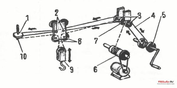
Rice. 1. Diagram of a crane that you can make yourself:
1 - block, 2 - boom, 3 - crane trolley, 4 - telescopic stand, 5 - paired angles, 6 - boom base blocks, 7 - I-beam, 8 - struts, 9 - crane trolley moving winch, 10 - load frame, 11 - lifting mechanism winch, 12 - electric winch drive, 13 - stand corner, 14,15 - bolts M 16, 16 - lifting hook assembled with a block.
The crane consists of a horizontal boom beam (the crane trolley moves along it) and vertical support posts made of steel pipes, to which horizontal beams are attached. The crane is collapsible, which allows you to move it from place to place.
Construction of crane stands.
They are made of pipes with a diameter of 140 mm. Their height can be increased up to 3 m using telescopic incoming pipes. To prevent the posts from sinking into the ground, corners are welded to the base. A horizontal beam is welded to the top of the supports - two corners x 65 x 10 mm connected together. A horizontal guide is attached to it from below with four bolts - an I-beam No. 20, having dimensions of 200 x 100 x 5.2 mm, 3000 mm long, along which the crane trolley moves.
The second pair of guide supports consists of two vertical pipes connected at the top and bottom. For greater stability, two inclined supports are welded to them, which in turn connect the racks with a rectangular frame. The latter prevents the crane from tipping over, as it serves as a base for laying sandbags or concrete blocks.
An important feature of a jib crane is its control. Those who will build and operate it need to know: the crane has a lifting and moving device. If necessary, any part can be lowered below the zero mark (into a pit or trench). The entire system of cables and pulleys of the lifting device is driven by an electric motor. The trolley is moved by a hand winch using a cable. One end of it is fixed to the trolley, then the cable goes through the block to the drum, makes five turns and, again passed through the blocks at the base and at the end of the boom, is fixed to the crane trolley.
The hook is lifted by a cable, fixed at one end to the winch and passing successively through the blocks of the base, boom and crane trolley; then the cable is lowered down, forms a loop on which a block with a hook is suspended, and is secured to the end of the boom through the block of the crane trolley.
Rice. 2. Diagram of the mechanism for lifting and moving the load:
1 - boom end block, 2 - cable fastening pin on the crane trolley, 3 - boom base blocks of the crane trolley moving mechanism, 4 - cable moving the crane trolley, 5 - drum, 6 - hoisting mechanism winch, 7 - hoisting mechanism boom base block , 8 - blocks of the maroon trolley, 9 - block of the hook, 10 - assembly for securing the lifting cable.
The lifting device can also be driven by a conventional manual winch, which will provide the crane with complete autonomy.
Before starting work, you should carefully check the strength of the nodes and supports. Standing under the boom is not allowed - this is the basic safety rule at any construction site.
We hope that there will be farmers and gardeners who will build a crane to make their work easier. Maybe not like that. But similar. The main thing is that he helps in the work.
The Pioneer crane is an indispensable machine during loading and unloading, installation and construction repair work. Depending on the size and volume of loading materials, it can be used and installed on the roofs of houses, in pits, as well as on the floors of buildings that are under construction.
This “miracle machine” consists of: a control panel (the control system is automated), a boom, an electric winch and two frames - a support and a rotary one. The Pioneer crane is a machine that is quite simple to operate and does not require any special physical effort. Even a person who is not experienced in construction can quite cope with operating the crane.

Design diagram
There is no need to register the Pioneer crane with the regulatory authorities. If there is a need to transport the crane to another place, there will be no problems with this either, since this machine is very convenient to transport.
terms of Use
The Pioneer crane does not require strict rules of use. It can work equally well on a hot summer day (air temperature +40 degrees Celsius) and in freezing cold (up to -40 degrees Celsius).
However, it is worth paying attention to the slope of the site where the crane will be located in the future. It should not exceed 3 degrees.
It’s quite calm, this machine can operate at a wind speed of 14 m/s. BUT: you should stop operating the crane if the wind speed is over 33 m/s.
My own master
Many owners of dachas or private houses make their own cranes. This is very convenient, since each mechanism (be it a simple motor or a full-fledged one) hydraulic drive) will be customized and adjusted to the person who made it. In addition, such a mechanism helps not only to carry heavy monolithic blocks, but also to deliver light loads, such as, to the top of the building.
Alas, it’s unlikely that you’ll be able to apply hydraulics to your creation. But it will be possible to replace it with an equally worthy homemade lifting machine that is not too difficult to use.
Many will probably have a completely adequate question: “Where can I get the parts?” The answer will be very short and unequivocal - at a landfill. If you push your innate disgust into the background and take a walk through many interesting landfills native land, then you can find a lot of useful things at a construction site.
So, in order to create a Pioneer crane with your own hands, the first thing you need to do is find an I-beam and rectangular pipe. Immediately, the condition is stipulated that the I-beam must fit freely into the pipe. It is placed on sliding guides, and thus a telescopic unit is obtained.
During use, in order to reduce friction, the sliding guides must be lubricated!
In order for the crane to finally be able to function, it must be equipped with certain cables of the smallest diameter. You will already have to spend money on them in the specialized hardware store(though you might also have luck finding them in a landfill). You can use the channel as a material for welding the support and rotary frames. It is the channel that allows for good fixation of the crane on the surface. Usually, the roof of the object that is being built is this surface.
In order for work with the machine to proceed without incident, and also to protect yourself, it is necessary to weld a rectangular-shaped ballast pad.
One will be enough foundation block, to lift a load weighing half a ton. To start the lifting process, you can purchase an electric motor in a special store, and then connect it to a winch from a UAZ.

Connecting electrical mechanisms
To start the lifting mechanism electrically, you will have to use the services of an electrician. The connection procedure itself is not too complicated, but still, for your own safety, you should trust a person who has experience working with electricity.
After this, the DIY Pioneer crane is ready for use.
Specifications
To better understand what the above-mentioned representative of lifting machines is capable of, it is advisable to familiarize yourself with his more detailed description– Pioneer crane technical characteristics.
So, the first point in general characteristics crane is, of course, its lifting capacity. It can fluctuate in the range of 0.5 tons - 1 ton. The advantage of the Pioneer crane is that it is able to lift a load that is several times heavier than itself. The height of the crane is consistently 4 meters. The angle that the platform can cover when turning is 360 degrees.
The reference contour (connecting the contour of the vertical axes of the lifting machine, formed by horizontal projections of straight lines) is 2x2 meters. The speed of lifting the load is a floating value, depending on the mass of the load (0.5 tons - from 0.2 to 50 m/s; 1 ton - 0.74 m/s). The diameter of the rope also depends on the size of the load: 6.9 mm - 0.5 tons, 12 mm - 1 ton. The weight of the Pioneer crane, depending on the model, can be 1 – 1.5 tons.
Any user of the site will agree with the statement that one of the most necessary things during construction is a crane. The steel hero becomes an indispensable assistant when there is a need to lift a large load.
A lifting mechanism is usually associated with a huge structure tens of meters high. However, in private house-building, when compact mechanisms for construction come to the fore, one needs an option with a boom length not exceeding 5-7 meters.
But renting it is not a cheap pleasure, especially if the construction lasts for more than one month.
In this case, there is only one way out - roll up your sleeves and build a homemade mini-crane with your own hands. And our forum members will help you with this!
How to do homemade faucet
Saving on your own health and trying manually lift an unbearable load, especially if the construction of the house is carried out independently and without the involvement of hired labor work force, they don’t lead to any good. We have already told our readers. Now we are making a crane with our own hands to build a house called “ mini-pioneer."
"Pioneer" is a mobile collapsible design, with the help of which the load is lifted to a given height. So homemade The crane can be used when digging foundations and construction and installation work on building houses.
The basis of the mechanism is a supporting running frame, installed permanently or on a mobile chassis. The rotating part of the crane is mounted on the frame. The boom can be rotated manually or electrically. The crane design itself is made on a modular basis and can be disassembled into several parts for the convenience of moving the mechanism from one construction site to another.

The stability of the structure is ensured thanks to a counterweight and steel cable guys (turnbuckles), and the load is lifted using a winch and a block.
 The experience of our forum member, who decided to build a mini “Pioneer” on his own, is interesting. This construction mechanism he needed it to build a private house made of timber.
Voldemort:
“I am almost single-handedly building a house from six-meter timber. It is impossible to lift and carry it alone. That is why I decided to assemble a mechanism in order to take the timber from the stack, place it at the sawing site and lift it to the plinth.
As the height of the building increases, our forum member plans to place a crane on the floor beams of the house.
A forum member assembled the frame from a corner 63x63x5 mm. The 5-meter-long boom was made from a pipe with a diameter of 50 mm. To strengthen the structure, two corners 30x30x3 mm were used. Also included in the plans Voldemora includes further extension of the boom by another 2 meters.
Voldemort:
– The lifting capacity of the mechanism is approximately 150 kg, but the design can lift more weight, and in order to achieve this, it is necessary to increase the multiplicity of pulleys.
Translated from Greek, Polyspaston means “tensioned by several ropes.” They call it a chain hoist construction device for lifting loads. It consists of several blocks connected to each other by a rope or cable that goes around the blocks in a circle. A pulley block allows you to lift a load with less effort than the weight of the load.
The simplest pulley allows you to get a three-fourfold gain in strength; we should not forget that friction losses are inevitable in this system. Even in best models blocks they reach 10%. And the more you gain in strength, the more the distance over which the equipment can move the load decreases.

Voldemort:
– It took me a week to make all the components and mechanisms. I spent another two days assembling and fine-tuning the mechanism. The swing drive and the boom lift drive are a six-fold manual pulley. The lifting drive is also a manual double chain hoist.

Voldemort notes that it would be much more convenient to control a mechanism with electric drives - to lift the load from a remote control on a long cord, as is done in industrial models. But in this case, the complexity of manufacturing all the mechanisms increases significantly, which will lead to an increase in the cost of the design and an increase in the time for manufacturing the crane.
The details of the device's manufacture are interesting.
Voldemort:
– As a turntable, I took two faceplates that I found at work. Basically, I assembled the mechanism from what was at hand. Instead of an axle, I welded a 30 mm bolt. I did not take a bolt made of high-strength steel, because such ones weld worse, do not stretch or bend, and immediately burst if their strength limit is exceeded.
All components of the device are lubricated with lithol.


To reduce the weight of the counterweight, the length of the support legs is 2 meters. At self-production When calculating the components of such a device, one point should be taken into account. The fact is that with a radius of the rotating faceplate of 200 mm and a distance of 2 meters to a counterweight weighing 100 kg, a tensile load of 1 ton acts on the central bolt. And this does not take into account the weight of the boom and the load being lifted!

It is also important to check the device for stability.
Voldemort:
– To begin with, let’s imagine that our crane is a single beam that rests on one support, and this support should be the shortest distance from the axis of rotation. Three forces act on the beam: the weight of the load, the weight of the counterweight and the mass of the mechanism. In order not to take into account the mass of the boom, I underestimated the weight of the crane by 50 kg. The calculation is approximate and simple, but it is better with it than without it at all.
Boom lift drum Voldemort Made from a tube with a diameter of 100 mm.
Voldemort:
– There is a nuance here - the drum cannot be placed close to the blocks. It needs to be shifted slightly along the axis towards the first block so that the second layer of cable is wound evenly.
A forum member made the blocks from three washers: two large and one small. All blocks are without bearings. It is important to ensure that the blocks bend well with the rope. That is, either the rope must be flexible, or the blocks must be of large diameter. Otherwise, when the boom is raised without load, the cables may fly out of the blocks.

Voldemort:
– My rope has a diameter of 12 mm, but it is very thick - there was simply no other way. If I lengthen the boom, I will put more flexible cable with a diameter of 5 mm, because its working load is 150 kg, and its breaking load is 850 kg.
When designing block systems, it is important to understand how the chain hoist works and is calculated. Let's look at this using the example of a mini-pioneer.
Voldemort:
– The principle of operation of a pulley block is similar to the operation of a gearbox - you gain in strength, but lose in the length of the rope and, consequently, the speed of lifting the load.
In the gearbox main characteristic- This gear ratio, and in a chain hoist – the multiplicity, i.e. the ratio of all rope branches to those running off the drum. If we have 6 sections of rope, it means the chain hoist is six-fold.
This means that the pulling load on the drum will be 6 times less than the weight of the load, and the rope itself, if it is designed for 100 kg, then rolled 6 times, will lift 600 kg.


Do-it-yourself construction mini-cranes
The design turned out to be so successful that many of our users decided to repeat it and even give the crane mobility by placing it on a Gazelle.
Forum member with nickname plumag proposes using a similar mechanism with a higher load capacity and equipped with electric drives to install concrete pillars. And in order to be able to transport such an individual crane on the roads common use, make the structure collapsible and install it partially or completely in the body at the site of the proposed work. This will allow you to quickly recoup all costs associated with the manufacture of the device.
At FORUMHOUSE you can learn everything about self-help, and also get acquainted with the mini-pioneer. The portal discusses everything you need to know to make a faucet, from a concrete mixer to a pipe bender. Topics from forum members about making useful household items that will help you build.
Our video will tell you what tools you need to set up a carpentry workshop. See how to make A yourself in this tool, which will simplify work on your site near the country house.
Materials for the crane were mainly found in scrap metal. We only had to buy bearings, a winch, and order parts for the turning mechanism from a turner.
And I also had to pay the welder, since I myself welding work I can’t do it because of some vision problems.
In general, this crane cost 5,000 rubles, which cannot be compared with the amount of work that I managed to complete with its help, because the “cheapest” helper in our region costs 800 rubles per day.
I’ll immediately make a reservation that during operation, my faucet revealed some shortcomings, which I will point out and advise on how to correct them. So your faucet will be a little different from mine.
Let's start with the rotating mechanism

It consists of six parts that need to be ordered by a turner, and two bearings.

As you can see, there are no dimensions in the drawing. The fact is that Exact size, like mine, you don’t have to follow it at all. After all, we make the faucet from available material, and I cannot know what size channel or I-beam, or what kind of pipe you will have at hand.
A little more or a little less doesn’t matter in my design. And you will understand this from further instructions. And having generally estimated what materials and parts you have, determine what dimensions to take for the manufacture of the rotating mechanism.
The mechanism has two bearings. At the top, between the housing and the base, there is a support bearing. Below, again between the housing and the base, there is a simple radial bearing.


Or rather, the housing should be mounted on the bearing, and the base should fit into it. Thus, both of these parts are connected. For more reliable fixation of the radial bearing, a nut is screwed onto the housing from below. The thickness of the threaded and retaining parts of the nut is at your discretion, but not less than 3 mm.
Then this unit is attached to the platform with a bolt (I have an M 26), which attracts the base to the platform. Thus, it turns out that the platform and base are a stationary part of the mechanism, and the body with the nut is rotating.
Now a little about what practice has shown. Towards the end of the season, the radial bearing weakened a little, and a barely noticeable play formed in the turning mechanism.
But with a boom length of 5 meters, this play became noticeably noticeable, so I recommend installing a hub bearing, 36 mm wide, instead of a radial bearing.


Here in Kazan, support and wheel bearings can be bought for 500 rubles both. And to tighten the bolt securing the base to the platform, you will need a spanner with an extension, and definitely two washers - a flat one and a lock washer.
Our next node will be the rack.


To make it you will need a piece of pipe (I have d140) and four pieces of channel. The height of the stand needs to be estimated so that finished form she was just the thing for you. Even two centimeters lower. Then it will be convenient to turn the winch when operating the crane.
Since God is unlikely to send you a piece of pipe with an evenly cut end, you will have to cut one end yourself. To do this, we take a car clamp, or make a clamp from a strip of tin, and tighten it on the pipe.
When tightened, the clamp will try to position itself on the pipe as evenly as possible, and if you help it a little (by eye), you will get a fairly even line around the circumference of the pipe, which you just have to draw, then remove the clamp, and cut the pipe along this line using a grinder .
Then, the rotating mechanism platform is welded to this flat end of the pipe. Now it’s clear why I didn’t give the dimensions in the drawing? You still have to order the rotating mechanism. And you can find a tuba. This means the diameter of the platform can be ordered according to the diameter of the pipe.
Now the legs. They need to be welded so that the stand does not collapse. How to do it? Firstly, they need to be cut to the same length.
Then hang the pipe with the welded platform, passing the rope through the hole in the center of the platform, and place your legs diagonally to the pipe, so that in the end, the pipe remains hanging evenly, and the legs, with four sides rested against her.
As soon as the balance is found, you need to draw by eye the corners of the channels that abut the pipe, and trim them with a grinder as shown in the photo.
After trimming the corners, lean your legs against the pipe again, catch your balance, check with a rack and tape so that they form an even cross, and secure them with welding. After tacking, check the cross again, and you can weld.
All that remains is to make the support cross itself. It can be made from any rigid profile. At first there was an idea to put it on wheels made of bearings, but time was running out, and it didn’t come to the wheels, but actually it would have been nice. The unit turned out to be quite heavy, and it was difficult to move it.


The length of the arms of the cross is 1.7 meters, although as operation has shown, this cross does not play a particularly large role in the stability of the crane. The main stability is provided by balance, which we will talk about later.
The cross is not welded to the legs, but is attached with M 10 bolts and nuts. This was done for ease of possible transportation. The legs were reinforced in anticipation of installing wheels, but they never got around to it, although the idea of installing them is still there.
The stand with the rotating mechanism is ready, now let's move on to the crane platform, on which the counterweight, winches, and boom will be installed. For the platform I found a one and a half meter I-beam, 180 mm wide. But I think you can use a channel and even a 150 x 200 beam under it.

At first I even wanted to use timber, but since I found an I-beam, I chose it. The platform is attached to the rotary mechanism body with four bolts and M 10 nuts.


If you use timber instead of an I-beam, then you will need to make additional platforms for it, above and below. You can “encircle” it with two pieces of channel and tighten everything with bolts.
But we’ll wait with the bolts for now, since the place where the platform is attached to the rotating mechanism will need to be selected based on balance. That is, the crane boom must be balanced by a block for counterweights and a winch. That is, the crane must stand confidently on the stand and not fall over.
Next will be the counterweight block.


I have it made from pieces of the same channel as the platform, but it can be made from anything, and in any way. The main thing is to have a container in which you can install loads, so that if necessary, you can increase the counterweight.
Now about the winch. My winch is installed with a capacity of 500 kg, with a brake. And once again, as practice has shown, such power was not enough to lift a load of about 100 kg.
That is, you can lift it, but you have to lean so hard on the handle that when lifting to a height of more than 5 meters, you get tired very quickly. For such a crane you need a winch of 1 - 1.5 tons.
There was also supposed to be a second winch for lifting the boom, but it was at that time, having visited a bunch of shops and markets, that I could find only one winch with a brake, which you see in the photo. Therefore, instead of a second winch, a temporary tension cable was made, the length of which is still changed using clamps.


Unfortunately, there is nothing more permanent than a temporary structure. I still recommend that you install a winch instead, preferably a worm one. Its speed is low, and the brake, whether up or down, is dead. That's what an arrow needs.
All that remains is to make an arrow, which is what we will do. The boom consists of a mount with a shaft, a beam 150 x 50, and a tip with a pulley.


First - the mounting body. It is better to make it from a piece of channel wood.


Any round timber with a diameter of 20 to 30 mm will do for the shaft. For example, I cut off a piece of the rotor shaft of some old engine. Then we bend it in a vice, put two brackets around this shaft and fasten it to the channel, into which the beam will then be inserted.


We buy two simple bearings, so that they fit tightly onto the shaft, and cut out a seat in the mounting body.


Of course, you can dream up how to secure the bearings in the housing. Besides mine, there are probably a dozen more ways. And I found an ebonite plate, 10 mm thick, from which I made these fasteners.


The boom itself is a beam 150 x 50, 5 meters long. It is inserted into a channel 80 mm wide and 2.5 meters long. True, I had to trim it a little so that it would go inside the channel. I have a channel installed, 3.5 meters long, but this is only because I didn’t have it at hand at the time good timber, with small knots. I simply played it safe, which, unfortunately, increased the weight of the arrow.
The timber is secured to the channel with ties made from a metal strip 3 mm thick.

At the end of the boom, you need to attach a pulley for the cable. Mine is made from a wheel from a trolley bag. For skillful hands, I think there are plenty of options for attaching the pulley. At first it was fastened between two pieces of plywood, but then I made a fastening from a channel.


Now you can assemble the arrow, if not for one “but”. During operation, the brackets that secure the shaft to the channel turned out to be rather weak. So I made them stronger.


And one more addition. My reinforcing part is secured with four bolts. You need to add two more on top to make the knot more rigid. Although mine works fine with four bolts. Otherwise I would have added it long ago.
Now you can assemble the entire crane platform, that is, install a winch on it, a block for counterweights under the winch, and at the other end - a boom lifting body with a boom. If there is, then a second winch, if not, then a guy rope, like mine.
All this is assembled in a lying position, and upon completion it is raised vertically, onto some kind of support. For example, I stacked several pallets on top of each other and placed the assembled platform on them so that the counterweight hung freely downwards.
Then we attach the rotating mechanism to the stand. The most important thing remains - install the platform on the stand so that the boom and counterweight balance each other.
Unfortunately, I don’t have any photographs of the structure that I built for this, well, I’ll try to explain it this way.
This design is a tripod with a block at the top. The height of the tripod is approximately three meters. It is made from timber 100 x 50. As you probably already guessed, the assembled crane platform needs to be suspended and raised so that a stand can be placed under it.
The platform will be raised using its own winch. To do this, we pass the winch cable through the block and hook it to the boom lifting body, which is located at the opposite end of the platform.
Now, if you operate the winch upward, the entire platform will rise. But during the rise, the arrow, raised up, begins to collapse, so you need to either call a couple of assistants who will fix the arrow in a vertical position, or make another tripod (as I did) with a block 6 meters high, and tie rope to the end of the arrow, let it through the block, and pull it up as the platform rises.
Having suspended the platform in this way and placed a stand under it, you can lower and raise the platform and move the stand to find a position in which the counterweight will balance the boom.
In this position we drill 4 through holes and bolt the platform to the stand. OK it's all over Now. The tap is ready. You can start testing.
Well, a couple of examples of operation:


General view of my faucet:

If the article does not answer your question, ask it in the comments. I will try to answer as quickly as possible.
I wish you success in your work, as well as the opportunity to lift and move everything you need and where you need it.
Acceptable amount is from 10 rubles. up to 15,000 rub.
Homemade lifting devices are an indispensable tool for a garage where major car repairs are planned. With the help of this assistive device you can easily remove the car engine, lift the edge of the body, or even the entire car.
Easy to make homemade lifting mechanisms They make work several times easier and faster not only in the garage, but also near the house. They are indispensable for construction and repair, moving construction waste, and unloading heavy loads.
Types of lifting mechanisms
Before you start assembling a garage faucet with your own hands, you should choose which mechanism will suit you best. Load lifting machines belong to a fairly important category of industrial and household equipment. They are designed to move various loads in a vertical or inclined direction. A useful feature for motorists is the ability to move a load suspended on a hook to the side, thereby freeing up space for work. When designing a car lift, it is advisable to supplement it with a similar option - this way you can expand the list of actions performed in the garage.
Purchasing a ready-made lift entails significant financial costs, so many garage owners are interested in the question of how to make such a mechanism themselves. First you need to understand what types of devices exist, how they differ from each other, and what functions they have. Classification is made according to various signs: principle of operation, purpose, type of drive. Let's look at the most common types of lifting machines:
- Pulleys are manual mechanisms that use only the strength of human muscles to lift a load. The structure of the block is known from the school curriculum: it consists of a wheel with a recess around it, rotating around a fixed axis. A rope, rope or metal chain passes through the recess. The force required to lift weights decreases exponentially as the number of pulleys in the system increases.
- A jack is a simple lever device used to raise one side of a vehicle. Jacks can be either manual or hydraulic, pneumatic or electric.
- A hoist is a manual or mechanized device consisting of a system of interconnected blocks. Depending on the number of individual wheels (pulleys), hoists are divided into two-, three-, four-pulley, etc. The maximum number of pulleys that such devices use is 12. Industrial variety hoist - a chain hoist is often used to move cargo on ships.
In addition to standard lifting devices, there are specialized installations:
- The telpher is an improved hoist, equipped electrically driven. Thanks to this addition, the power and load-carrying capacity of the mechanism increases, and when the hoist is placed on a horizontal I-beam, it becomes possible to move loads along the room.
- The crane is a simple device that works on the principle of a lever. A hook is attached to one end of the lever for hanging a load, and a counterweight is attached to the opposite end. The height of lifting loads largely depends on the position of the mechanism itself, since the length of the lever stroke remains small. Using a crane, you can not only lift weights, but also move them along a trajectory described by the radius of the lever. Often a crane successfully replaces a crane, but due to its large dimensions, its use in a garage is not practiced.
What characteristics should a garage lift have?
Since the device will be used in the rather cramped conditions of a standard garage, certain requirements are put forward for it. Firstly, it should not be too large - such a car lift, despite its high power, takes up a lot of space, which is very undesirable in such a small area. Secondly, it is recommended to give preference to mechanisms with a small vertical stroke, otherwise you risk running into the ceiling.
The second requirement is carrying capacity. It is calculated based on the types of work for which the car lift is being developed. The dimensions of the mechanism also depend on the purpose. If a regular jack is suitable for regular wheel replacement, then for larger-scale work you will need a car lift with a platform, although for such important actions it is recommended to resort to the help of professional equipment.
Materials and tools
When constructing a garage lift with your own hands, you need to have in your arsenal not only drawings of the future device, but also arm yourself with a set of tools and high-quality, load-resistant materials. First of all you will need: 
- welding machine;
- grinder with cutting wheel for metal;
- bolts and nuts for fastening;
- steel pipes with a diameter of 40-50 mm;
- steel angle or profiled pipe with a cross section of 35-40 mm;
- cable;
- homemade winch for a garage (you can also purchase it; the factory-produced version will be more reliable).
As the planned homemade garage winch becomes a reality, the list of components for it may change slightly, depending on your specific requirements for the mechanism.


