Installation of an additional hydraulic accumulator to the pumping station. Types of hydraulic accumulators and features of their connection to different pumps. Preliminary check and pressure correction
The most important element The pumping station is a hydraulic accumulator.
The scheme for connecting it to the well depends on the degree of autonomy of the water supply and the absence or presence of a water heater in the water supply network.
Let's consider possible options installations, as well as the design and types of hydraulic accumulators.
 In the very simple design A hydraulic accumulator (HA) is a container installed at a certain height (above any of the consumers) and equipped with level sensors.
An example of such a device is a water tower that supplies water supply network in some rural locality.
In autonomous water supply systems of private houses, such a HA is usually installed in the attic.
The pressure in the taps is provided by the weight of the liquid column; level sensors or a float switch control the operation of the pump.
Modern pumping stations use more advanced hydraulic pumps, which can be installed at any level - even below water intake points. The volume of such a device is divided into two parts: one is pumped with water from the water supply system, the other contains air with some excess pressure (pumped by a pump through a regular spool).
Both parts are separated by an elastic element, so when one of them is filled with water, the volume of the second decreases, and accordingly the pressure of the air in it increases. It is the air pressure that performs in such a hydraulic system the same function as gravity in a water tower - it provides pressure in the system.
Structurally, GAs are divided into two types:
- Membrane: the volumes for water and air in such tanks are separated by a rubber membrane. There are membrane tanks designed for use in closed systems heating. They are designed for lower pressure than HA for water supply, and they use technical rubber, not food grade rubber. To avoid confusion, it is customary to paint HA for heating red, and for water supply - blue.
- Cylinder: a rubber bag with a flange is inserted inside such a storage device, which is connected to the water supply. Thus, in balloon HAs, water does not come into contact with the metal walls of the housing at all. In addition, replacing the cylinder is not difficult and can be easily done by the user, while in some models you have to contact a service center to replace the membrane.
The volume of HA can vary greatly - from 24 to 1000 liters or more. It should be taken into account that the passport shows the total volume of the tank including the air chamber.
As for the volume of water that the tank can hold, it will depend on the settings of the pressure switch for the amount of air pumped in.
So, with relay settings of 1 atm/2 atm (on/off pressure) and an air pressure of 0.8 atm (checked with an empty cylinder), 30 liters of water will fit in a 100-liter GA.
If the shutdown pressure is raised to 2.5 atm, the storage capacity will increase to 38.5 liters.
In HAs with a volume of over 100 liters, a valve is installed in the upper part of the water chamber to release air, which is released from the liquid during operation and gradually accumulates. Tanks with a smaller volume do not have such a valve and must be emptied periodically to get rid of accumulated air.
GA can have horizontal and vertical version. The device and operating principle of both varieties are completely identical; the choice of one or another model depends solely on the ease of installation.
 The hydraulic accumulator has an extremely simple device; you can also connect it yourself. - Recommendations for selection and installation, read carefully.
Place in the water supply system
 If the operation of the domestic water supply was provided by only one pump, it would have to be turned on every time as soon as one of the users opened the tap.
Such a mode would lead to the rapid exhaustion of the electric motor's life, since the starting moment is the most difficult for it.
The pump passport even indicates such a parameter as the maximum permissible switching frequency.
Even for the most durable electric motors, it is no more than 15 starts per hour, for all others - 10 or less.
This is what determines the use of GA. It accumulates not only water, but also the pressure necessary for comfortable use of the water supply. At the same time, the operating mode of the pump looks completely different: it runs longer, but - most importantly - turns on less often.
At the same time, the membrane or balloon storage device performs another important function: it acts as a damper, smoothing out water hammer.
However, HA is not always needed in water supply systems. Here are the cases in which you can do without it:
- If water is used in long cycles: a typical example is watering the garden. Here GA is not only not needed, it is contraindicated. The water supply in it will be used up very quickly and the pump will have to be turned on frequently to replenish it. In the absence of a HA, the unit will operate quietly in a stable mode.
- If the pump is equipped with the latest automation, which provides the function of smoothly starting the engine and regulating its power depending on the pressure in the system.
Connection diagram for a hydraulic accumulator for water supply systems
The method of connecting the HA will depend on the features and purpose of the pumping station. Let's consider three options.
Option 1
 The pump supplies water from a well, borehole or storage tank, while only cold water supply is provided.
In this case, the HA is installed inside the house in any convenient place.
Typically, it, a pressure switch and a pressure gauge are connected using a five-pin fitting - a piece of pipe with three bends that cuts into the water supply.
To protect the HA from vibrations, it is connected to the fitting with a flexible adapter. To check the pressure in the air chamber, as well as to remove air accumulated in the water chamber, the HA must be periodically emptied. Water can be drained through any water tap, but for convenience, the drain valve can be cut through a tee into the supply pipeline somewhere near the tank.
Option 2
The house is connected to centralized water supply, and the pumping station is used to increase the pressure. With this method of application, the HA stations are connected in front of the pump.
In this case, it is designed to compensate for the decrease in pressure in the external line at the moment the electric motor starts. With this connection scheme, the volume of the HA is determined by the power of the pump and the magnitude of pressure surges in the external network.

Installation of a hydraulic accumulator - diagram
Option 3
Connected to water supply storage water heater. The HA should be connected to the boiler. In this embodiment, it can be used to compensate for the increase in water volume in the heater due to thermal expansion.
Diagram for connecting a hydraulic accumulator to a submersible pump
If the pressure characteristic of a submersible pump allows maintaining acceptable pressure at water points in combination with sufficient performance, the HA is connected according to the usual scheme using a five-terminal or three-terminal fitting.
However, wells can be very deep, and their dimensions often do not allow the installation of a pump of sufficient power (for example, 3-inch wells).

Connecting a hydraulic accumulator with your own hands
In such cases, the following scheme is used:
- A submersible unit is installed in the well, the power of which is only sufficient to lift water to the surface.
- Near the well, on the surface or in the ground, a HA is installed in the form of a simple container equipped with level sensors. These sensors control the operation of the submersible pump.
- A self-priming pump is installed near the storage tank (if it is buried in the ground) or normal suction (if the HA is installed on the surface), which supplies water directly to the home water supply. In this case, a membrane or balloon HA is installed in the house, and the pump is controlled by a pressure switch.
Electrical diagram for connecting the pressure switch to the hydraulic accumulator
Typically, pressure switches for household pumping stations have two groups of contacts, but sometimes you come across models with one.Each group consists of two pairs, and both pairs are closed or opened simultaneously. The contacts in each pair are labeled, for example, “Line/Load” or “Line/Motor”.
In principle, it is not necessary to follow these notations. You can even, for example, connect wires from the network to the “Line” contact of one pair and the “Load” contact of the other.
The main thing is that both wires are not connected to the contacts of one pair - this will lead to short circuit. The wires leading to the pump motor should be connected to the remaining two contacts. It is desirable that the colors of the braids of the cores connected to one pair match. Before connecting the power cord, make sure it is not plugged into a power outlet.
To connect the grounding conductor (usually it has a yellow-green braid) there is a screw on the relay body, marked with the corresponding symbol.
When connecting the wire from the relay to the pump motor, the blue-braided wire should be connected to the “zero” contact, and the red or black wire to the “phase” contact.
Often, for reliability, the grounding contacts of the pump and the relay are connected to each other, but this is not necessary.

Pressure switch in a water supply system with a deep pump
Square cross section The wire cores must correspond to the power of the electric motor. For copper wire the cross-section is selected at the rate of 1 sq. mm for every 8 A of current. To determine the current strength in a single-phase network, it is necessary to divide the power of the electric motor by 220. So, for example, in the circuit of an electric motor with a power of 1.5 kW, a current of 1500/220 = 6.8 A will flow.
It is important not to confuse the diameter of the wire core and its cross-sectional area, since these values can be comparable. For example, the cross-sectional area of a core with a diameter of 1.5 mm is 1.76 square meters. mm.
Please note that the electrical connection must be made only after connecting the pressure switch to the water supply.
 Nowadays, the lack of centralized water supply is no longer such a problem. a big problem. Big variety pumping equipment allows you to arrange autonomous system water supply without special labor. , installation and repair, read on.
You will find a water supply diagram for a private house with a storage tank in the topic.
Video on the topic
An indispensable device in modern systems water supply is not only a pump. Very often it is supplemented with a hydraulic accumulator, which can be included with the pump or purchased and installed separately.
Installing a hydraulic accumulator is very useful solution which improves the quality of work. Let's take a closer look at exactly how this mechanism works, how it works and how it is mounted.
1 The design of the hydraulic accumulator and the principle of its operation
First, we will describe the device of a hydraulic accumulator: it is a container with a metal casing, inside of which there is a membrane (or a cylinder, depending on the design). Pressure is created between it and the walls of the housing - thanks to compressed air pumped into the space.
Most often, the installation is used in water supply, but it is also important to use a hydraulic accumulator for heating - it is also suitable for this.
The objectives of the mechanism are as follows:


- Water accumulation.
- Maintaining stable pressure in the system.
- Providing water to the system when the pump is not running.
The operating principle is as follows: water enters the membrane, pumped by a pump. The membrane is filled and fills the space inside the housing (naturally, to a certain volume).
On the other hand, the pumped air begins to put pressure on the water, thereby displacing it into the water supply system. In this case, the pump operates up to a certain point - until the water pressure inside the tank reaches a certain limit.
After this, the unit turns off, and the air acting on it begins to “squeeze” water into the network. Well, when the liquid leaves the container and the pressure drops to a certain (only now minimum) level, the pump will start working again from the automatic control unit.
1.1 Classification
The range of products on the market is quite extensive, so it will be useful for the buyer to find out in advance what exactly they are, how they are classified, and which model is best to choose.
The differences lie in a number of factors, each of which should be mentioned.


According to the location of the container, the device can be either horizontal or vertical.
There may also be differences in the type of working part. In this regard, there are two variations: membrane or balloon. In the first case, the space inside the container is divided into two parts by a membrane: water flows into one, air is pumped into the second.
In the second case, an elastic cylinder is contained inside the container, into which liquid flows, and air is pumped into the free space between its walls and the walls of the body.
Separately, it is necessary to mention the volume - this is, in fact, the key parameter of any capacity. The most popular sizes are 24, 50, 100 and 200 liters. However, you can also find containers of other sizes on sale - 6, 12, or vice versa - 300 liters.
There are also larger devices - for example, the Aquasystem hydraulic accumulator, which can have a volume of up to 2000 liters. The Reflex hydraulic accumulator has a smaller capacity - largest model has a volume of 1000 liters. The Wester hydraulic accumulator has the same limits.
The material from which the membrane (balloon) is made also deserves detailed attention. It can be either butyl or rubber. The differences are quite serious:


- butyl has an upper temperature limit at +99 degrees;
- for rubber this mark is lower - only +50 degrees.
This is very important nuance for those who choose a heating device. However, most often devices from modern manufacturers (the same Aquasystem hydraulic accumulator) use butyl.
And finally, we need to mention the manufacturers of products of this type. Several items that are most popular have already been mentioned above. This is a Wester and Aquasystem hydraulic accumulator. Models of these brands are included in the high-budget segment, but the quality is appropriate.
The Reflex hydraulic accumulator is already cheaper, but at the same time it is practically not inferior in quality. In addition to these names, we can also highlight Gilex, which is quite popular on Russian market their positive qualities: low cost and reliability.
1.2 How to correctly calculate the volume of a hydraulic accumulator?
In principle, the main point that deserves attention is the volume of the tank. The material of the membrane (cylinder) was also mentioned above, however, such devices are used less frequently for heating, so we will focus on capacity.
It should be said right away that models with a capacity of several hundred liters (for example, the Aquasystem VAV 2000 hydraulic accumulator for 2000 liters or the Wester Line WAV 1000 hydraulic accumulator for 1000 liters) are suitable for providing water large buildings(hotels, hospitals - for example).


For an ordinary residential building, this volume will be a lot, and buying such a model will be a waste of money. Moreover, they cost quite a lot: for example, the mentioned Wester Line WAV 1000 hydraulic accumulator will cost more than 10 thousand dollars, and the Aquasystem VAV 2000 hydraulic accumulator will cost three dozen.
For a cottage in which 3-4 people permanently live, a capacity of up to 100-200 liters will be sufficient (and this is with a huge margin). Often, buyers in such conditions are limited to models of 24-50 liters (for example, the Aquasystem VAV 50 hydraulic accumulator or the Wester Line WAV 50 hydraulic accumulator).
An increase to 100-200 liters is relevant if there are more inhabitants in the house, and/or there is a large number of water intake points (2 toilets and 5-10 taps, for example). In this case, you should pay attention to the Wester Line WAV 100 hydraulic accumulator or the Aquasystem VAV 100 hydraulic accumulator.
For accuracy, we provide a more detailed calculation that will help the buyer more accurately select the appropriate device.
2 Stages and nuances of installation
We figured out how to perform the calculation and how to choose a device. Now we need to mention how exactly the hydraulic accumulator is connected to the water supply system. If you wish, you can do this work yourself - if you follow the tips below, then there should be no difficulties.
In this case, it does not matter which model is connected - a Reflex hydraulic accumulator for a couple of tens of liters or a tank for 300 liters.
The preparation looks like this:


- First of all, you need to choose the place where the equipment will be located: an automatic water supply station and, in fact, the tank itself. They do not have to be placed next to each other, but most often this is how it is done.
- The pressure inside the container is checked. It is necessary that this indicator be approximately 0.2-1 atmospheres lower than the parameter set on the automatic pump start relay. Otherwise, you can (and should) adjust it yourself.
Now you need to take care of the necessary details for connection:
- A fitting with 5 outputs: for the tank itself, for the relay automatic switching on, for the pressure gauge, for the pump and, in fact, for the water line itself.
- Pressure gauge (with a scale up to 10 atmospheres).
- FUM tape (for sealing joints).
Now let’s look at how you can make the connection yourself:
- The fitting is connected to the container using a hose.
- A pressure gauge, relay, pump, etc. are connected to other outputs of the fitting. Each connection is pre-sealed with FUM tape.
Upon completion of work, you should perform a test run of the pump to determine the tightness of the system. To do this, you need to carefully inspect the connection points: there should be no leaks along them.
When connecting the pressure switch with your own hands, be sure to look very carefully at the marks that are marked under its cover. There are two of them - these are "Network" and "Pump", and under no circumstances should they be confused. It is possible that these marks will not appear at all (this happens with some models) - in this case, it is recommended not to make the connection yourself, but to use the help of an electrician.
2.1 How does a hydraulic accumulator work? (video)
For home autonomous water supply It is important to ensure stable pressure in the network. This will reduce inefficient pump operation. Also, when you open the tap, water will flow immediately, without any delay.
Water hammer should not be allowed to occur in the water supply system. Such phenomena destroy not only plumbing system, but also adjacent units, for example, a boiler heat exchanger or disable dishwashers. To get rid of any negative factors, you need to know how to connect a hydraulic accumulator to a submersible pump.
Hydraulic accumulator design
As a rule, the exterior of these devices is painted blue or a light blue tint to distinguish it from expansion tanks that have a red outer surface. Components hydraulic device are the following elements:
- metal case;
- membrane made of rubberized material;
- a lid with a valve for filling the cavity with liquid;
- nipple assembly used for pumping compressed air;
- legs with holes for mounting bolts to ensure stability on a level platform.
Hydraulic accumulators are usually called metal hollow vessels that have a membrane inside, fixed to inside housings. It is a water storage device. The membrane cavity is filled either clean air, or a mixture of inert gases. To know how to choose the right hydraulic accumulator for a well and water supply, you need to consider that the operating pressure inside the filled membrane is about 1.5 atm. This value is maintained throughout the entire period of operation of the device.
.png)
Design diagram
Before connecting the hydraulic accumulator to the system, it is filled with inert gas or just air. This operation is performed using a standard automobile pump. If the value has been pumped, it is enough to bleed off excess air through the nipple.
When water enters the tank, the bulb is prevented from bursting. It also helps regulate systemic pressure.
There are three most popular groups of hydraulic accumulators:
- Cold. Used on highways with cold water. Works effectively in protecting against wear and during smoothing out water hammer.
- Hot. Performs all the same functions as cold, but is able to withstand aggressive temperature environments.
- For heating. This type is only relevant in heating systems closed type.
Battery performance
The hydraulic accumulator connection diagram includes a chain of a water supply pump, a main pipeline and the fluid accumulator itself. Water is supplied directly into the rubber membrane located in the cavity metal product. The procedure stops after achieving parity in pressure values.
As a rule, the values on the pressure gauge in such a situation are 1-3 atm. Having entered the generator operating mode, the automation turns off the pump.
When a consumer opens a tap or starts dishwasher, the water accumulated in the accumulator cavity moves into the water supply system, since the pressure there has become less than in the accumulator. This happens gradually, and at the stage when the pressure level in the cavity has reached a certain set point (the setting is made by the manufacturer or consumer of the product), the relay is turned on, connecting the makeup water pump. Through it, the membrane is again filled with water. Such cycles occur almost constantly. Before setting up the accumulator and relay, you should read the detailed instructions.

Interested in how to properly connect a hydraulic accumulator for water supply, many forget about the importance of its volume. The larger size of the tank allows you to use the pump less often, because with low water flow rates there is no refilling every time. The pressure difference between the maximum and minimum values is quite large.
Application of surface pump
To know how to properly install a hydraulic accumulator in a water supply system, it is worth studying the step-by-step auxiliary instructions:
- It all starts with checking the air pressure inside the gas cavity in the battery. The value must be brought to such a figure that it is 0.2...1.0 less than the minimum set by the relay manufacturer.
- Work is being done with a fitting that has 5 outputs, since the hydraulic accumulator will need to be connected to a pressure gauge, relay, and pump. The last exit is relevant for connecting a water pipe.
- The fitting allocated for the procedure is connected to the tank. To do this, you will need a rigid hose that has an air bypass valve in its design.
- We tighten the remaining devices with the necessary force so as not to break the threads.
After installation, the module must be tested under high pressure to identify possible leaks in connections.
Before setting up the hydraulic accumulator and connecting the relay responsible for regulating the pressure to it, you will need to familiarize yourself with the installation marks on the latter. The contacts are labeled “network” and “pump”. It is undesirable to make mistakes with the electrical connection, so as not to damage the unit.

Since the vessel operates under high pressure, it is necessary to maintain maximum sealing in all threaded connections. For this purpose, the use of FUM tape or the use of technical flax is suitable. They are capable of maintaining a connection up to several atmospheres, which is typical for household hydraulic systems.
Model selection
There are models of household hydraulic accumulators on sale from 24 liters to 1000 liters. You need to start from what fluid flow needs to be provided, as well as whether the system is used for irrigation.
As a rule, a capacity of 24 is enough for the needs of two people. The kitchen, toilet and watering are taken into account small area. For increased requirements, it is recommended to use cavities of 50 liters. In this case, the number of consumers is calculated. The container can be changed at any convenient time for a larger one, because the connecting nodes of most models have the same thread parameters.
Use of pumping stations
If it is not possible to collect individual elements in the chain, you can purchase a pumping station. This is a fully assembled unit, which includes:
- surface centrifugal pump;
- pressure meter;
- automatic relay.
When connecting the hydraulic accumulator, it is necessary to completely de-energize the equipment. The operating pressure is 2-2.5 atm, after injection of which it is necessary to check the equipment for leaks and proper switching.
Why do we need another hydraulic accumulator?
An additional hydraulic accumulator provides the most optimal mode work. The fact is that a centrifugal pump, like any other, when turned on more than 6-7 times a minute, fails 3-4 times faster. The built-in hydraulic accumulator is designed to equalize the difference in pressure between the unit being turned on and off, while the additional one will compensate for the difference, stabilize the operation of the equipment when turned on frequently and increase the pressure in the system.
Vertical or horizontal?
The design of both vertical and horizontal hydraulic accumulators is absolutely identical, so the choice of any of them is a purely personal matter. Whichever one fits certain conditions needs to be installed. With a small amount free space vertical is preferable.
Where do you buy pumps, pumping stations and components?
.jpg)
All elements necessary for water supply are sold in construction and specialized stores. It is also fashionable to order them online, but carefully check the performance of the equipment.
Be sure to obtain a warranty. Complex instruments, including surface and deep well pumps, often fails for reasons beyond the control of the consumer.
VIDEO: Why is there a hydraulic accumulator in the water supply system?
Today it is unthinkable to imagine a house without a water supply system. But sometimes there are cases when water cannot always reach one or another water point. Then a hydraulic accumulator comes to the rescue, regulating the pressure in the network. Next we will talk about which scheme for connecting a hydraulic accumulator to a water supply system is effective.
Hydraulic accumulator device

For normal operation of the water supply system in the house, in some cases, a hydraulic accumulator is installed on a section of the network, which is a container with a metal casing. Inside the tank there is a rubber “bulb” that acts as a membrane. The hydraulic accumulator, which is a link in the water supply system, accumulates a certain volume of water under pressure. When operating plumbing fixtures, a dishwasher or washing machine, the hydraulic accumulator supplies the network with water.
The rubber membrane is fixed to the container body with a flange, the design of which includes an inlet pipe. Inside, the accumulator is designed in such a way that between the inner walls of the cylinder and the rubber “bulb” there is air, which is compressed after it is pumped into the container by a pump - bicycle or car. When water is pumped into the tank, the volume of which is limited by the bulb, compressed air counteracts further expansion of the elastic rubber, thereby protecting it from rupture. In this case, compressed air provides the necessary pressure in the network.

If we take into account the design of a standard hydraulic accumulator, we can distinguish the following components:
- housing, which is a hermetically manufactured tank, which is designed for operating pressure in the range of 1.5–6 atmospheres. This value can be increased to 10 atmospheres under short-term load conditions;
- “pear”, which is an elastic membrane. It is attached to the inlet part of the tank and is located inside the cylinder. Water enters through a flow flange, which is equipped with a valve and is fixed to the neck of the accumulator tank.
- nipple, which is located on the other side of the body - opposite to the location of the flow flange. The nipple is designed to pump air through it into the battery space, which is formed between the outer surface of the “pear” and the walls of the housing on the inside.
In addition to the main elements, legs located at the bottom of the housing are welded to the drive for stability, and support bracket for installation of a pumping unit surface type, which is located at the top of the cylinder.

Depending on the place of application, hydraulic accumulators are divided into:
- products for working in cold water supply systems;
- devices for functioning in the hot water supply network;
- expansion tanks for heating systems.
Hydraulic accumulator for supply cold water it is designed in such a way that it accumulates and supplies liquid, and also has the ability to avoid water hammer in the network and protect the pumping unit from unnecessary switching on. An analogue that supplies consumers with hot water has the same characteristics as the above product. The difference lies only in the properties of the membrane, which can withstand high temperatures. Purpose expansion tank in heating systems lies in compensation possibilities in cases of water expansion.
Operating principle of a hydraulic accumulator

The water supply system, in the circuit of which there is a hydraulic accumulator, operates according to a certain scheme.
- Starting from the water intake, which can be a water supply system, a well or a well, water is supplied through a pipeline to the battery, namely, to the rubber “bulb”.
- In the rubber membrane, using a control relay that determines the lower and upper threshold of the required parameter, the pump creates a pressure, for example, 1–3 atmospheres.
- Once the pressure in the device reaches the set value, the pump automatically turns off.
- After the consumer opens the faucet on the sink or turns on dishwasher, the membrane begins to push water out of the accumulator and supply it through the network to the water distribution point.
- When the pressure in the device drops to a critically low level, the relay is activated and the pump automatically starts working. But first you need to connect the pump to the hydraulic accumulator.
The number of pump starts per unit time directly depends on the volume of the cylinder. The smaller the tank, the more frequently the pump will turn on. With this option, the pump and flange with valve will quickly run out of working resources. Since the cylinder is not affected by external loads, it does not need to be additionally fixed to the floor. To ensure the stability of the hydraulic accumulator, its own legs are enough.
Options with a choice of hydraulic accumulator

There are hydraulic accumulators different designs and volumes - from compact devices of 24 liters to large products of 1000 liters. When choosing a storage tank, you need to take into account the volume of water that is used by consumers in the house. If no more than two people live in the house and a minimum of plumbing fixtures and household items are installed, then it is enough to purchase a tank with a volume of 24 liters. If, based on various factors, the water consumption is high, then a hydraulic accumulator must be installed bigger size and volume. It is necessary to calculate how many water points can operate simultaneously and, based on the calculated flow rate, select suitable container. If the water supply system is already equipped, and the situation in the house has changed - the number of residents has increased or, for example, washing machine, then you need to change the battery to a larger one or deliver another tank.
Connection diagram for the version with a surface pump

Before connecting the hydraulic accumulator for water supply, you need to check the air pressure in the tank. It should be less than the pump pressure when turned on, which is set on the relay, by a value of up to 1 bar. To connect the tank to the pump, you need to purchase a fitting with 5 outlets, a relay that regulates the pressure, a pressure gauge and sealant in the form of tow or FUM tape.
- One of important details When installing a hydraulic accumulator, there is a fitting with 5 outlets. Through this part, a pump, relay and pressure gauge are connected to the tank. Another 1 fitting outlet is intended for connecting a water supply system, which branches to water intake points. On initial stage the fitting is connected to the container through a rigid hose or directly through a flow flange with a valve. Then an adjustable relay and pressure gauge are screwed to the separating part, as well as a pipe that is routed further from the pump.
- Particular attention must be paid to connecting the relay that controls pressure. The device has a top cover that needs to be removed. Under it there will be 4 contacts with the inscriptions “network” and “pump”. Thanks to their presence, it is difficult to confuse the connection of wires. According to the marks, the wires connected from the pump and going to the network are connected.
Not all manufacturers put labels on relays, relying on the knowledge of the installer. If the person connecting the relay does not know which contact to connect this or that wire, it is better to contact a professional electrician.
All threaded connections must be carefully sealed. Tow or FUM tape are suitable for this work. Finally, you need to turn on the pump unit, after which you need to visually and by touch check the installation sites for leaks.
Connection diagram for the version with a submersible pump

Already from the name you can understand that submersible pump is placed in the aquatic environment of a well or well, from where water is supplied directly to the hydraulic accumulator. A water supply system with such a pump must be equipped check valve. This part prevents water from returning after the membrane to the deep water intake. As a rule, the check valve is mounted directly on the pump, while the other end is connected to the pressure pipeline. There are varieties of pumps in which the fitting on the cover has internal thread. Then during installation you need to use a part on which 2 external threads are cut. Following the check valve there is a pipe that is laid to the hydraulic accumulator.
When installing the pump, you need to take into account that the unit should not reach the bottom of the well or well by approximately 30 cm.
Video
The video provided clearly shows how the pump is connected to the accumulator.
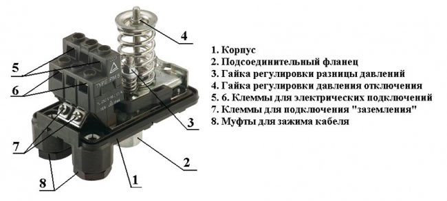
The pressure switch for the hydraulic accumulator is fully responsible for its operating mode and the frequency of activation of the pump. This is the main control device of the system. The entire water supply scheme is closely related to the values set on it. It is this element that gives the signal to the electric pump to turn on or off.
Place of the device in the water supply system
(GA) consists of a container, a valve for bleeding, a flange, a 5-pin fitting (tee) with couplings for connection, as well as a pressure switch (control unit), which sets the rhythm of all work.
- main control element
- ensures work without overloads
- controls optimal filling of the tank with water
- extends the service life of the membrane and all equipment in general
A pressure gauge that shows the pressure in the tank is included in the kit or can be purchased separately.

The pump pumps water out of the well and directs it through pipes. Next, it enters the GA, and from it into the home pipeline. Task membrane tank– maintain stable pressure, as well as the pump operating cycle. There is a certain maximum activation for it - about 30 per hour. When exceeded, the mechanism experiences loads and through a short time may fail. The water pressure switch must be adjusted so that the devices operate as expected, without exceeding the critical load.
Under setting storage tank imply the creation of the required number of atmospheres in itself and the correct setting of pump response thresholds
Design and principle of operation
The device looks like a box various shapes with controls under the cover. It is attached to one of the outlets of the fitting (tee) of the container. The mechanism is equipped with small springs that are adjusted by turning the nuts.
Operating principle in order:
- The springs are connected to a membrane that responds to pressure surges. An increase in indicators compresses the spiral, a decrease leads to stretching.
- The contact group reacts to these actions by closing or opening the contacts, thereby transmitting a signal to the pump. The connection diagram necessarily takes into account the connections of its electrical cable to the device.
- The storage space fills up and the pressure increases. The spring transmits the pressure force, the device operates according to the set values and turns off the pump, sending it a command to do so.
- The liquid is consumed - the pressure weakens. This is fixed, the engine turns on.
The assembly consists of the following parts: a housing (plastic or metal), a membrane with a cover, a brass piston, threaded pins, metal plates, cable sleeves, terminal blocks, a hinged platform, sensitive springs, and a contact assembly.
The operating algorithm of the control device is as simple as possible. The mechanism responds to changes in the number of atmospheres inside the drive. The moving platform is raised or lowered by springs depending on the pressure on the piston, which in turn interacts with contacts that signal the pump to start or stop pumping.
Installation
Often the HA kit is sold disassembled, and the control unit must be installed yourself.
Connecting the pressure switch to the hydraulic accumulator looks like this in stages:
- The station is disconnected from the network. If water has already been pumped into the storage tank, it is drained.
- The device is fixed permanently. It is screwed onto the 5-pin fitting of the unit or onto the outlet pipe and must be firmly fixed.
- The wiring diagram is normal: there are contacts for the network, pump, and grounding. The cables are passed through holes on the housing and connected to contact blocks with terminals.

Electrical connection to the pump
Settings
Before adjusting the relay, you need to take into account that its values are inextricably linked with the pressure inside the membrane tank. First you need to create the required amount of pressure inside it, and then move on to working with the control in question.
The adjustment is carried out in 3 stages:
- pressure inside HA
- pump start level
- shutdown mark
For optimal performance it is necessary to adjust the parameters several times experimentally, taking into account the water flow, the height of the pipes and the pressure in them.
Indicators inside the accumulator
It is advisable that the pressure adjustment in the accumulator take into account the following examples and rules:
- For one-story house 1 bar is enough, and if the tank is installed in the basement, then add 1 more
- the value must be greater than at the highest point of water intake
- how many atmospheres should be inside the container is determined by the following formula: add 6 to the height of the pipes to the highest point of water intake and divide the result by 10
- if there are many consumption points or the branching of the pipeline is significant, then a little more is added to the resulting figure. How much to add is determined empirically. For this there is next rule. If the value is too low, then water will not be delivered to the devices. If it is too high, the HA will be constantly empty, the pressure will be too strong, and there will also be a risk of membrane rupture.
In order to increase the pressure in the accumulator, air is pumped up with an ordinary bicycle pump (there is a special spool on the body); to lower it, it is vented. The pneumatic valve for this purpose is located under the decorative trim. The procedure must be done in the absence of water pressure, which requires simply closing the taps.

The value of the indicators is determined by a pressure gauge connected to the spool. The correction is made after the pump has turned off. The pressure difference is created by opening the tap at the nearest point.
Manufacturers standardly set the pressure in the tank to 1,5 – 2,5 bar. Its increase reduces the usable space inside the container and increases the pressure in the system - this must be taken into account when calculating.
Basics of adjusting thresholds
There are two springs with nuts: the larger one is responsible for the values for turning off the pump, the smaller one is for turning it on. The bolts are loosened or tightened, thereby making adjustments.
Setting up the accumulator pressure switch will be of high quality if you follow these rules:
- the average recommended difference between the values for turning the pump on and off is 1 - 1.5 atm
- the pressure inside the HA must be lower than the set value to turn on the pump by 10%. Example: if the activation mark is set to 2.5 bar, and the switch off mark is set to 3.5 bar, then there should be 2.3 bar inside the container
- the hydraulic accumulator and control unit have their own load limits - when purchasing, you need to check whether they coincide with the calculations for the system (pipe height, number of intake points, flow rate)
The mechanism in question controls the maximum and minimum pressure in the tank. It maintains the difference in its values when the station is activated and switched off. The limit of its settings depends on the power and hourly flow rate of the pump.
Factory parameters are indicated in the product data sheet. Usually they are like this:
- limit limits – 1 – 5 atm
- pump operating range – 2.5 atm
- starting point – 1.5 atm
- maximum switch-off level – 5 atm
Preparation and example of setting the required values
Preparation:
- tank is connected
- the control unit is adjusted under pressure, the system is not disconnected from the power supply
- inside the unit the pressure should be 10 - 13% lower than that of the pumping station. That is, approximately 0.6 - 0.9 atm than the mark at which the engine turns on
- all taps are closed
- the set level is checked with a pressure gauge within an hour to make sure there are no leaks
- remove the block housing cover to have access to the nuts and observe the springs

Setting with an example of setting marks of 3.2 atm to turn off and 1.9 atm to turn on (two-story house):
- Start the pump to determine the pressure in the system. It should fill the storage part of the device and increase the pressure.
- They determine at what pressure gauge reading the shutdown will occur (usually no more than 2 atm.) When exceeded, a small spring comes into action, which is clearly visible.
- The motor is stopped above 3.2 - 3.3 atm, this figure is reduced by rotating the nut on the small spring a quarter turn, since it is very sensitive, until the motor turns on.
- They check with a pressure gauge: 3 - 3.2 atm will be enough.
- Turn on the tap to relieve the pressure and so that the HA is freed from the liquid and record the pump activation mark with a pressure gauge, usually 2.5 atm - the lower pressure indicator has been reached.
- To reduce the lower threshold, rotate the large spring bolt counterclockwise. Next, start the pump until the pressure rises to the required level, after which you need to check the pressure with a pressure gauge. An acceptable value is 1.8 - 1.9 atm. When “failure” occurs, the nut is rotated clockwise.
- Once again, adjust the small spring a little, clarifying the already set thresholds.
The adjustment bolts are very sensitive - turning just 3/4 of a turn can add 1 atm. The pressure of the switched-on pump should be 0.1 - 0.3 atm higher than in an empty storage tank, which will prevent damage to the “bulb” inside it.
The setup process in brief
For a better understanding of how to set up a pressure switch, we will outline the process more clearly:
- pump activation mark (minimum pressure): rotating the large spring bolt clockwise increases the starting mark, counterclockwise decreases it;
- value for shutdown: move the small spring, when tightening - the pressure difference increases, when unscrewing - the actuation mark decreases;
- the result is checked by opening the tap and draining the water, recording the moment the pump is turned on;
- The internal pressure force is adjusted by deflating or pumping air and checking this with a pressure gauge.
Increasing the factory switching parameters (above 1.5 atm) creates a risk of critical load on the hydraulic tank membrane. The operating range of the pump is adjusted taking into account the maximum possible load for water fittings. The sealing rings of household taps can withstand a maximum of 6 atm.
Maintenance, problems, operation
Preventative actions and repairs:
- mechanical sensitive parts need to be checked and adjusted
- It is advisable to clean the contacts
- If it doesn’t work, don’t rush to disassemble the mechanism - first try lightly tapping the body with a not too heavy object
- Rocker joints are lubricated with grease once a year
- do not tighten the adjustment nuts completely - the mechanism will not work
If the device does not hold pressure, does not work correctly, or does not work at all, refrain from hasty conclusions and do not throw it away. Dust, debris, sand in the membrane space prevent it from reacting normally. Steps to fix the problem are:
- Unscrew the 4 bolts on the bottom, remove the cover with the inlet pipe and the cover.
- Carefully rinse the membrane and the cavities around it.
- Install all elements in reverse order.
- Set the thresholds again and carry out a test run.
Experts recommend that before setting up the relay correctly, do not exceed the upper threshold by more than 80% of the maximum permissible values for a specific model, which are indicated in the instructions (standard about 5 - 5.5 atm.).
For quality work there should be no air in the pipeline. Periodically (once every 3-6 months) you need to check the set response thresholds, pressure indicators in the HA, and bleed or pump in air. Before you start setting up, you need to find out whether the pressure switch for the hydraulic accumulator and the unit itself can withstand the required loads, and whether its technical capabilities meet them.

")


