Homemade hovercraft. Amateur hovercraft. Such a model will be reliable if
The high speed characteristics and amphibious capabilities of hovercraft, as well as the comparative simplicity of their designs, attract the attention of amateur designers. IN last years Many small WUAs have appeared, built independently and used for sports, tourism or business trips.
In some countries, such as the UK, USA and Canada, serial industrial production small WUAs; We offer ready-made devices or kits of parts for self-assembly.
A typical sports AVP is compact, simple in design, has lifting and movement systems independent from each other, and can be easily moved both above ground and above water. These are mainly single-seat vehicles with carburetor motorcycles or light car engines air cooling.
Tourist WUAs are more complex in design. They are usually two- or four-seater, designed for relatively long trips and, accordingly, have luggage racks, large-capacity fuel tanks, and devices to protect passengers from bad weather.
For economic purposes, small platforms are used, adapted for transporting mainly agricultural goods over rough and swampy terrain.
Main characteristics
Amateur AVPs are characterized by the main dimensions, mass, diameter of the supercharger and propeller, and the distance from the center of mass of the AVP to the center of its aerodynamic drag.In table 1 compares the most important technical data of the most popular English amateur AVPs. The table allows you to navigate wide range values of individual parameters and use them for comparative analysis with your own projects.
The lightest WUAs weigh about 100 kg, the heaviest - more than 1000 kg. Naturally, the smaller the mass of the device, the less engine power is required to move it, or the higher the performance can be achieved with the same power consumption.
Below are the most typical data on the mass of individual components that make up the total mass of an amateur AVP: air-cooled carburetor engine - 20-70 kg; axial blower. (pump) - 15 kg, centrifugal pump- 20 kg; propeller - 6-8 kg; motor frame - 5-8 kg; transmission - 5-8 kg; propeller ring-nozzle - 3-5 kg; controls - 5-7 kg; body - 50-80 kg; fuel tanks and gas lines - 5-8 kg; seat - 5 kg.
The total carrying capacity is determined by calculation depending on the number of passengers, a given amount of cargo transported, fuel and oil reserves necessary to ensure the required cruising range.
In parallel with calculating the mass of the AVP, an accurate calculation of the position of the center of gravity is required, since the driving performance, stability and controllability of the device depend on this. The main condition is that the resultant of the forces supporting the air cushion passes through the common center of gravity (CG) of the apparatus. It is necessary to take into account that all masses that change their value during operation (such as fuel, passengers, cargo) must be placed close to the CG of the device so as not to cause its movement.
The center of gravity of the device is determined by calculation according to the drawing of the side projection of the device, where the centers of gravity of individual units, structural components of passengers and cargo are plotted (Fig. 1). Knowing the masses G i and the coordinates (relative to the coordinate axes) x i and y i of their centers of gravity, we can determine the position of the CG of the entire apparatus using the formulas:

The designed amateur AVP must meet certain operational, design and technological requirements. The basis for creating a design and construction of a new type of WUA is, first of all, the initial data and technical specifications, which determine the type of apparatus, its purpose, total weight, carrying capacity, dimensions, type of main power plant, driving characteristics and specific features.
Tourist and sports WUAs, as well as other types of amateur WUAs, are required to be easy to manufacture, use readily available materials and assemblies in the design, as well as complete safety of operation.
Speaking about driving characteristics, they mean the hovering height of the AVP and the ability to overcome obstacles associated with this quality, maximum speed and throttle response, as well as braking distance, stability, controllability, and range.
In the design of the AVP, the shape of the body plays a fundamental role (Fig. 2), which is a compromise between:
- a) round contours in plan, which are characterized the best parameters air cushion while hovering in place;
- b) teardrop-shaped contours, which is preferable from the point of view of reducing aerodynamic drag when moving;
- c) a hull shape pointed at the nose (“beak-shaped”), optimal from a hydrodynamic point of view when moving along a rough water surface;
- d) a form that is optimal for operational purposes.
Using statistical data on existing structures that correspond to the newly created type of WUA, the designer must establish:
- weight of the apparatus G, kg;
- air cushion area S, m2;
- length, width and outline of the body in plan;
- lifting system motor power N v.p. , kW;
- traction motor power N motor, kW.
- pressure in the air cushion P v.p. = G:S;
- specific power of the lifting system q v.p. = G:N ch. .
- specific power of the traction motor q dv = G:N dv, and also begin developing the AVP configuration.
The principle of creating an air cushion, superchargers
Most often, when constructing amateur AVPs, two schemes for forming an air cushion are used: chamber and nozzle.In a chamber design, most often used in simple designs, the volumetric flow rate of air passing through the air path of the device is equal to the volumetric flow rate of the supercharger
![]()
Where:
F is the perimeter area of the gap between the supporting surface and the lower edge of the apparatus body, through which air exits from under the apparatus, m 2 ; it can be defined as the product of the perimeter of the air cushion fence P and the gap h e between the fence and the supporting surface; usually h 2 = 0.7÷0.8h, where h is the hovering height of the apparatus, m;
υ - speed of air flow from under the apparatus; with sufficient accuracy it can be calculated using the formula:

where R v.p. - pressure in the air cushion, Pa; g - acceleration free fall, m/s 2 ; y - air density, kg/m3.
The power required to create an air cushion in a chamber circuit is determined by the approximate formula:
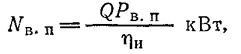
where R v.p. - pressure behind the supercharger (in the receiver), Pa; η n - coefficient useful action supercharger.
Air cushion pressure and air flow are the main parameters of the air cushion. Their values depend primarily on the size of the apparatus, i.e., on the mass and bearing surface, on the hovering altitude, the speed of movement, the method of creating an air cushion and the resistance in the air path.
The most economical hovercraft are AVPs large sizes or large load-bearing surfaces, in which the minimum pressure in the cushion allows a sufficiently large load capacity to be obtained. However, independent construction of a large-sized apparatus is associated with difficulties in transportation and storage, and is also limited by the financial capabilities of the amateur designer. When reducing the size of the AVP, a significant increase in pressure in the air cushion is required and, accordingly, an increase in power consumption.
Negative phenomena, in turn, depend on the pressure in the air cushion and the speed of air flow from under the device: splashing while moving over water and dust when moving over a sandy surface or loose snow.
Apparently, a successful WUA design is, in a sense, a compromise between the contradictory dependencies described above.
In order to reduce the power consumption for the passage of air through the air channel from the supercharger into the cushion cavity, it must have minimal aerodynamic resistance (Fig. 3). The power losses that are inevitable when air passes through the channels of the air tract are of two types: losses due to the movement of air in straight channels of constant cross-section and local losses during expansion and bending of the channels.
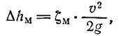
In the air tract of small amateur AVPs, losses due to the movement of air flows along straight channels of constant cross-section are relatively small due to the insignificant length of these channels, as well as the thorough treatment of their surface. These losses can be estimated using the formula:

where: λ - pressure loss coefficient per channel length, calculated according to the graph shown in Fig. 4, depending on the Reynolds number Re=(υ·d):v, υ - speed of air passage in the channel, m/s; l - channel length, m; d is the diameter of the channel, m (if the channel has a cross-section other than circular, then d is the diameter of an equivalent area cross section cylindrical channel); v is the coefficient of kinematic viscosity of air, m 2 /s.
Local power losses associated with a strong increase or decrease in the cross-section of the channels and significant changes in the direction of air flow, as well as losses for air suction into the supercharger, nozzles and rudders constitute the main costs of supercharger power.
Here ζ m is the coefficient local losses, depending on the Reynolds number, which is determined by the geometric parameters of the loss source and the speed of air passage (Fig. 5-8).
The supercharger in the AVP must create a certain air pressure in the air cushion, taking into account the power consumption to overcome the resistance of the channels to the air flow. In some cases, part of the air flow is also used to generate horizontal thrust of the device in order to provide movement.
The total pressure created by the supercharger is the sum of static and dynamic pressure:
![]()
Depending on the type of AVP, the area of the air cushion, the lifting height of the device and the magnitude of losses, the components p sυ and p dυ vary. This determines the choice of type and performance of superchargers.
In a chamber air cushion circuit, the static pressure p sυ required to create lift can be equated to the static pressure behind the supercharger, the power of which is determined by the formula given above.
When calculating the required power of an AVP supercharger with a flexible air cushion enclosure (nozzle design), the static pressure behind the supercharger can be calculated using the approximate formula:
where: R v.p. - pressure in the air cushion under the bottom of the apparatus, kg/m2; kp is the pressure drop coefficient between the air cushion and the channels (receiver), equal to k p =P p:P v.p. (P p - pressure in the air channels behind the supercharger). The k p value ranges from 1.25÷1.5.
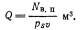
The volumetric air flow rate of the supercharger can be calculated using the formula:
Adjustment of the performance (flow rate) of AVP superchargers is carried out most often - by changing the rotation speed or (less often) by throttling the air flow in the channels using the rotary dampers located in them.
After calculated required power supercharger, you need to find an engine for it; Most often, hobbyists use motorcycle engines if power up to 22 kW is required. In this case, 0.7-0.8 of the maximum engine power indicated in the motorcycle passport is taken as the calculated power. It is necessary to provide intensive cooling of the engine and thorough cleaning of the air entering through the carburetor. It is also important to obtain a unit with a minimum weight, which consists of the weight of the engine, the transmission between the supercharger and the engine, as well as the weight of the supercharger itself.
Depending on the type of AVP, engines with a displacement from 50 to 750 cm 3 are used.
In amateur AVPs, both axial and centrifugal superchargers are used equally. Axial blowers are intended for small and simple structures, centrifugal blowers are intended for air pumps with significant pressure in the air cushion.
Axial blowers typically have four blades or more (Figure 9). They are usually made of wood (four-blade blowers) or metal (multi-blade blowers). If they are made of aluminum alloys, then the rotors can be cast and also welded; you can make them a welded structure from steel sheet. The pressure range created by axial four-blade superchargers is 600-800 Pa (about 1000 Pa with a large number of blades); The efficiency of these superchargers reaches 90%.
Centrifugal blowers are made of welded metal construction or molded from fiberglass. The blades are made bent from a thin sheet or with a profiled cross section. Centrifugal blowers create pressure up to 3000 Pa, and their efficiency reaches 83%.
Selection of traction complex
Propulsors that create horizontal thrust can be divided mainly into three types: air, water and wheel (Fig. 10).Air propulsion means an aircraft-type propeller with or without a nozzle ring, an axial or centrifugal supercharger, as well as an air-jet propulsion unit. In the simplest designs, horizontal thrust can sometimes be created by tilting the AVP and using the resulting horizontal component of the force of the air flow flowing from the air cushion. The air propulsion device is convenient for amphibious vehicles that do not have contact with the supporting surface.
If we are talking about WUAs moving only above the surface of the water, then a propeller or water-jet propulsion can be used. Compared to air engines, these thrusters make it possible to obtain significantly more thrust for each kilowatt of power expended.
The approximate value of thrust developed by various propulsors can be estimated from the data shown in Fig. eleven.
When selecting propeller elements, one should take into account all types of resistance that arise during the movement of the propeller. Aerodynamic drag is calculated using the formula
![]()
The water resistance caused by the formation of waves when the WUA moves through the water can be calculated using the formula

Where:
V - speed of movement of the WUA, m/s; G is the mass of the AVP, kg; L is the length of the air cushion, m; ρ is the density of water, kg s 2 /m 4 (at a sea water temperature of +4°C it is 104, river water is 102);
C x is the aerodynamic drag coefficient, depending on the shape of the vehicle; is determined by purging AVP models in wind tunnels. Approximately we can take C x =0.3÷0.5;
S is the cross-sectional area of the WUA - its projection onto a plane perpendicular to the direction of movement, m 2 ;
E is the coefficient of wave resistance, depending on the speed of the airfoil (Froude number Fr=V:√ g·L) and the ratio of the dimensions of the air cushion L:B (Fig. 12).
As an example in table. Figure 2 shows the calculation of resistance depending on the speed of movement for a device with length L = 2.83 m and B = 1.41 m.

Knowing the resistance to movement of the device, it is possible to calculate the engine power required to ensure its movement at a given speed (at in this example 120 km/h), taking the propeller efficiency η p equal to 0.6, and the transmission efficiency from the engine to the propeller η p = 0.9:
A two-blade propeller is most often used as an air propulsion device for amateur AVPs (Fig. 13).
The blank for such a screw can be glued together from plywood, ash or pine plates. The edge, as well as the ends of the blades, which are exposed to the mechanical action of solid particles or sand sucked in along with the air flow, are protected by a frame made of sheet brass.
Four-blade propellers are also used. The number of blades depends on the operating conditions and the purpose of the propeller - for developing high speed or creating significant traction force at the moment of launch. A two-bladed propeller with wide blades can also provide sufficient traction. The thrust force, as a rule, increases if the propeller operates in a profiled nozzle ring.
The finished propeller must be balanced, mainly statically, before being mounted on the motor shaft. Otherwise, when it rotates, vibrations occur, which can lead to damage to the entire device. Balancing with an accuracy of 1 g is quite sufficient for amateurs. In addition to balancing the propeller, check its runout relative to the axis of rotation.
General layout
One of the main tasks of the designer is to connect all the units into one functional whole. When designing a vehicle, the designer is obliged to provide space within the hull for the crew and placement of lifting and propulsion system units. It is important to use already known AVP designs as a prototype. In Fig. Figures 14 and 15 show the design diagrams of two typical amateur-built WUAs.In most WUAs, the body is a load-bearing element, a single structure. It contains the main power plant units, air ducts, control devices and the driver’s cabin. The driver's cabins will be located in the bow or central part of the vehicle, depending on where the supercharger is located - behind the cabin or in front of it. If the AVP is multi-seat, the cabin is usually located in the middle part of the device, which allows it to be operated with a different number of people on board without changing the alignment.
In small amateur AVPs, the driver’s seat is most often open, protected in front by a windshield. The devices have more complex design(tourist type) cabins are covered with a dome made of transparent plastic. To accommodate the necessary equipment and supplies, the volumes available on the sides of the cabin and under the seats are used.
At air engines AVP control is carried out using either rudders placed in the air flow behind the propeller, or guide devices mounted in the air flow flowing from the air-breathing propulsion unit. Control of the device from the driver's seat can be of an aviation type - using handles or steering wheel levers, or as in a car - with a steering wheel and pedals.
There are two main types of fuel systems used in amateur AVPs; with gravity fuel supply and with an automobile or aviation type fuel pump. Fuel system parts, such as valves, filters, oil system with tanks (if a four-stroke engine is used), oil coolers, filters, water cooling system (if it is a water-cooled engine), are usually selected from existing aircraft or automobile parts.
Exhaust gases from the engine are always discharged into the rear of the vehicle and never into the cushion. To reduce the noise that occurs during the operation of WUAs, especially near populated areas, automobile-type mufflers are used.
In the simplest designs, the lower part of the body serves as the chassis. The role of the chassis can be performed by wooden runners (or runners), which take on the load when in contact with the surface. In tourist WUAs, which are heavier than sports ones, wheeled chassis are mounted, which facilitate the movement of WUAs during stops. Typically, two wheels are used, installed on the sides or along the longitudinal axis of the WUA. The wheels have contact with the surface only after the lifting system stops operating, when the AVP touches the surface.
Materials and manufacturing technology
For the production of AVP wooden structure They use high-quality pine lumber, similar to that used in aircraft construction, as well as birch plywood, ash, beech and linden wood. For gluing wood, waterproof glue with high physical and mechanical properties is used.For flexible fencing, technical fabrics are predominantly used; they must be extremely durable, resistant to atmospheric influence and humidity, as well as to friction. In Poland, fire-resistant fabric coated with plastic-like polyvinyl chloride is most often used.
It is important to perform the cutting correctly and ensure careful connection of the panels to each other, as well as their fastening to the device. To fasten the shell of the flexible fence to the body, metal strips are used, which, using bolts, evenly press the fabric against the body of the device.
When designing the shape of a flexible air cushion enclosure, one should not forget about Pascal's law, which states: air pressure spreads in all directions with the same force. Therefore, the shell of a flexible fence in an inflated state should have the shape of a cylinder or a sphere or a combination of both.
Housing design and strength
Forces from the cargo transported by the device, the weight of the power plant mechanisms, etc. are transferred to the body of the AVP, and also loads from external forces, impacts of the bottom on the wave and pressure in the air cushion. Basic structure The hull of an amateur AVP is most often a flat pontoon, which is supported by pressure in the air cushion, and in the swimming mode provides buoyancy to the hull. The body is subject to concentrated forces, bending and torque moments from the engines (Fig. 16), as well as gyroscopic moments from the rotating parts of the mechanisms that arise when maneuvering the AVP.The most widespread are two structural types of amateur AVP buildings (or combinations thereof):
- truss structure, when the overall strength of the hull is ensured with the help of flat or spatial trusses, and the skin is intended only to retain air in the air path and create buoyancy volumes;
- with load-bearing cladding, when the overall strength of the hull is ensured external cladding, working together with the longitudinal and transverse set.
The design of the cabin and its glazing must allow the driver and passengers to quickly exit the cabin, especially in the event of an accident or fire. The location of the glass should provide the driver with good review: the observation line must be between 15° down and 45° up from the horizontal line; lateral visibility must be at least 90° on each side.
Power transmission to propeller and supercharger
The easiest ones for amateur production are V-belt and chain drives. However, a chain drive is used only to drive propellers or superchargers whose rotation axes are located horizontally, and even then only if it is possible to select the appropriate motorcycle sprockets, since their manufacture is quite difficult.In the case of V-belt transmission, to ensure the durability of the belts, the diameters of the pulleys should be selected as maximum, however, the peripheral speed of the belts should not exceed 25 m/s.
Design of the lifting complex and flexible fencing
The lifting complex consists of a blower unit, air channels, a receiver and a flexible air cushion enclosure (in nozzle circuits). The channels through which air is supplied from the blower to the flexible enclosure must be designed taking into account the requirements of aerodynamics and ensure minimal pressure loss.Flexible fencing for amateur WUAs usually has a simplified shape and design. In Fig. Figure 18 shows examples of design diagrams of flexible fences and a method for checking the shape of the flexible fence after its installation on the device body. Fences of this type have good elasticity, and due to their rounded shape they do not cling to uneven supporting surfaces.
The calculation of superchargers, both axial and centrifugal, is quite complex and can only be done using special literature.
The steering device, as a rule, consists of a steering wheel or pedals, a system of levers (or cable wiring) connected to a vertical rudder, and sometimes to a horizontal rudder - the elevator.
The control can be made in the form of a car or motorcycle steering wheel. Taking into account, however, the specifics of the design and operation of the AVP as an aircraft, they often use the aircraft design of controls in the form of a lever or pedals. In its simplest form (Fig. 19), when the handle is tilted to the side, the movement is transmitted through a lever attached to the pipe to the elements of the steering cable wiring and then to the rudder. The forward and backward movements of the handle, made possible by its hinged design, are transmitted through a pusher running inside the tube to the elevator wiring.
With pedal control, regardless of its design, it is necessary to provide the ability to move either the seat or the pedals to adjust it in accordance with the individual characteristics of the driver. Levers are most often made of duralumin, transmission pipes are attached to the body using brackets. The movement of the levers is limited by the openings of the cutouts in the guides mounted on the sides of the apparatus.
An example of the design of a rudder in the case of its placement in the air flow thrown by the propeller is shown in Fig. 20.
The rudders can be either completely rotary, or consist of two parts - a fixed part (stabilizer) and a rotary one (rudder blade) with different percentage ratios of the chords of these parts. The cross-sectional profiles of any type of steering wheel must be symmetrical. The steering stabilizer is usually fixedly mounted on the body; The main load-bearing element of the stabilizer is the spar, to which the rudder blade is hinged. Elevators, very rarely found in amateur AVPs, are designed according to the same principles and are sometimes even exactly the same as rudders.
The structural elements that transmit movement from the controls to the steering wheels and throttle valves of engines usually consist of levers, rods, cables, etc. With the help of rods, as a rule, forces are transmitted in both directions, while cables work only for traction. Most often, amateur AVPs use combined systems - with cables and pushers.
From the editor
More and more close attention Fans of water sports and tourism enjoy hovercraft. With relatively little power input, they allow you to achieve high speeds; shallow and impassable rivers are accessible to them; A hovercraft can hover both above the ground and over the ice.For the first time, we introduced readers to the issues of designing small hovercraft back in the 4th issue (1965), publishing an article by Yu. A. Budnitsky “Soaring ships”. B was published short essay development of foreign hovercraft, including a description of a number of sports and recreational modern 1- and 2-seater hovercraft. The editors introduced the experience of independently building such a device by Riga resident O. O. Petersons in. The publication about this amateur design aroused particularly great interest among our readers. Many of them wanted to build the same amphibian and asked for the necessary literature.
This year, the Sudostroenie publishing house is releasing a book by Polish engineer Jerzy Ben, “Models and Amateur Hovercraft.” In it you will find a presentation of the basic theory of the formation of an air cushion and the mechanics of movement on it. The author provides the calculated relationships that are necessary when independently designing the simplest hovercraft, introduces the trends and prospects for the development of this type of vessel. The book provides many examples of the designs of amateur hovercraft (AHVs) built in the UK, Canada, USA, France, and Poland. The book is addressed to a wide range of fans of self-building ships, ship modellers, and watercraft enthusiasts. Its text is richly illustrated with drawings, drawings and photographs.
The magazine publishes an abbreviated translation of a chapter from this book.
The four most popular foreign hovercrafts
American hovercraft "Airskat-240"
Double sports hovercraft with a transverse symmetrical arrangement of seats. Mechanical installation - car. dv. Volkswagen with a power of 38 kW, driving an axial four-blade supercharger and a two-blade propeller in a ring. The hovercraft is controlled along the course using a lever connected to a system of rudders located in the flow behind the propeller. Electrical equipment 12 V. Engine start - electric starter. Dimensions of the device are 4.4x1.98x1.42 m. Air cushion area - 7.8 m 2; propeller diameter 1.16 m, total weight - 463 kg, maximum speed on water 64 km/h.American hovercraft from Skimmers Inc.
A kind of single-seat hovercraft scooter. The housing design is based on the idea of using a car camera. Two-cylinder motorcycle engine with a power of 4.4 kW. Dimensions of the device are 2.9x1.8x0.9 m. Air cushion area - 4.0 m 2; total weight - 181 kg. Maximum speed - 29 km/h.English hovercraft "Air Ryder"
This two-seater sports apparatus is one of the most popular among amateur boatbuilders. The axial supercharger is driven by the motorcycle engine. working volume 250 cm3. The propeller is two-bladed, wooden; Powered by a separate 24 kW motor. Electrical equipment with a voltage of 12 V with an aircraft battery. Engine start is electric starter. The device has dimensions of 3.81x1.98x2.23 m; ground clearance 0.03 m; rise 0.077 m; pillow area 6.5 m2; empty weight 181 kg. Develops a speed of 57 km/h on water, 80 km/h on land; overcomes slopes up to 15°.Table 1 shows the data for a single-seat modification of the device.
English SVP "Hovercat"
A light tourist boat for five to six people. There are two modifications: “MK-1” and “MK-2”. A centrifugal supercharger with a diameter of 1.1 m is driven by the vehicle. dv. Volkswagen has a displacement of 1584 cm 3 and consumes power of 34 kW at 3600 rpm.In the MK-1 modification, movement is carried out using a propeller with a diameter of 1.98 m, driven by a second engine of the same type.
In the MK-2 modification, a car is used for horizontal traction. dv. Porsche 912 with a volume of 1582 cm 3 and a power of 67 kW. The apparatus is controlled using aerodynamic rudders placed in the flow behind the propeller. Electrical equipment with a voltage of 12 V. Dimensions of the device 8.28 x 3.93 x 2.23 m. Air cushion area 32 m 2, total weight of the device 2040 kg, speed of modification "MK-1" - 47 km/h, "MK-2" - 55 km/h
Notes
1. A simplified method for selecting a propeller based on a known drag value, rotational speed and forward speed is given in.2. Calculations of V-belt and chain drives can be performed using standards generally accepted in domestic mechanical engineering.
Good day everyone. I would like to present to you my SVP model, made in a month. I apologize right away, the photo in the introduction is not exactly the same photo, but it also relates to this article. Intrigue...
Retreat
Good day everyone. I want to start with how I became interested in radio modeling. A little more than a year ago, for his fifth birthday, he gave his child a hovercraft

Everything was fine, they charged and rode until a certain point. While the son, secluded in his room with a toy, decided to put the antenna from the remote control into the propeller and turn it on. The propeller shattered into small pieces; he did not punish him, since the child himself was upset and the whole toy was ruined.
Knowing that we have a World of Hobby store in our city, I went there, and where else! They didn’t have the required propeller (the old one was 100mm), and the smallest one they had was 6’x 4’, two pieces, forward and reverse rotation. There is nothing to do, I took what I have. Having cut them to the required size, I installed them on the toy, but the traction was no longer the same. And a week later we had ship-modeling competitions, at which my son and I were also present as spectators. And that’s it, that spark and craving for modeling and flying was ignited. After which I became acquainted with this site and ordered parts for the first aircraft. True, before that I made a small mistake by buying a remote control in a store for 3500, and not PF in the region of 900 + delivery. While waiting for a parcel from China, I flew on a simulator using an audio cable.
Four aircraft were built during the year:
- Sandwich Mustang P-51D, span 900mm. (crashed on first flight, equipment removed),
- Cessna 182 made of ceiling and polystyrene foam, span 1020mm. (beaten, killed, but alive, equipment removed)
- Airplane "Don Quixote" made of ceiling and polystyrene foam, span 1500mm. (broken three times, two wings re-glued, now I’m flying on it)
- Extra 300 from the ceiling, span 800mm (broken, awaiting repair)
- Built
Since I have always been attracted by water, ships, boats and everything connected with them, I decided to build a hovercraft. After searching the Internet, I found the site model-hovercraft.com about the construction of the Griffon 2000TD hovercraft.


Construction process:
Initially, the body was made from 4mm plywood, sawed everything out, glued it together, and after weighing it, abandoned the idea with plywood (weight was 2,600 kg), and it was also planned to cover it with fiberglass, plus electronics.
It was decided to make the body from polystyrene foam (insulation, hereinafter penoplex) covered with fiberglass. A sheet of penoplex 20mm thick was cut into two 10mm pieces.

The body is cut out and glued, after which it is covered with fiberglass (1 sq. m., epoxy 750 g.)

The superstructures were also made from 5mm polystyrene foam; before painting, all surfaces and parts made of foam were treated with epoxy resin, after which I painted everything with acrylic spray paint. True, in several places the penoplex was slightly eaten away, but not critical.

The material for the flexible fencing (hereinafter referred to as SKIRT) was first chosen to be rubberized fabric (oilcloth from a pharmacy). But again, due to the large weight, it was replaced with dense water-repellent fabric. Using the patterns, a skirt was cut and sewn for the future SVP.


The skirt and body were glued together with UHU Por glue. I installed the motor with a regulator from the Patrol one and tested the skirt, I was pleased with the result. The rise of the hovercraft body from the floor is 70-80mm,


I tested the running ability on carpet and linoleum and was pleased with the result.
The diffuser guard for the main propeller was made of polystyrene foam covered with fiberglass. The rudder was made from a ruler and bamboo skewers glued together with Poxipol.

We also used all available means: 50 cm rulers, 2-4 mm balsa, bamboo skewers, toothpicks, 16 kV copper wire, tape, etc. Small parts made (hatch hinges, handles, handrails, spotlight, anchor, box for anchor line, container life raft on a stand, mast, radar, wiper arms with wipers) for more detailed model.


The stand for the main motor is also made of ruler and balsa.

The ship had running lights. A white LED and a red flashing LED were installed in the mast, since the yellow one was not found. On the sides of the cabin there are red and green running lights in specially made housings.

Lighting power control is carried out via a toggle switch activated by a servo machine HXT900
The traction motor reverse unit was separately assembled and installed, using two limit switches and one HXT900 servo machine


There are a lot of photos in the first part of the video.
Sea trials were carried out in three stages.
The first stage, running around the apartment, but due to the considerable size of the vessel (0.5 sq. m.) it is not very convenient to roll around the rooms. There were no special issues; everything went as usual.
Second stage, sea trials on land. The weather is clear, temperature +2...+4, side wind across the road 8-10m/s with gusts up to 12-14m/s, the asphalt surface is dry. When turning in the wind, the model skids very much (there was not enough runway). But when turning against the wind, everything is quite predictable. It has good straightness with a slight trim of the steering wheel to the left. After 8 minutes of use on asphalt, no signs of wear were found on the skirt. But still, it was not built for asphalt. It generates a lot of dust from under itself.
The third stage is the most interesting in my opinion. Tests on water. Weather: clear, temperature 0...+2, wind 4-6 m/s, pond with small thickets of grass. For the convenience of video recording, I switched the channel from ch1 to ch4. At the start, taking off from the water, the ship easily sailed over the surface of the water, slightly disturbing the pond. Steering is quite confident, although, in my opinion, the steering wheels need to be made wider (the ruler width was 50cm). The splashes of water don't even reach the middle of the skirt. Several times I ran into grass growing from under the water, I overcame the obstacle without difficulty, although on land I got stuck in the grass.
Stage four, snow and ice. All that remains is to wait for snow and ice to complete this stage in full. I think it will be possible to reach in the snow maximum speed on this model.
Components used in the model:
- (Mode2 - gas LEFT, 9 channels, version 2). HF module and receiver (8 channels) - 1 set
- Turnigy L2205-1350 (injection motor) - 1 pc.
- for brushless motors Turnigy AE-25A (for injection motor) - 1 pc.
- TURNIGY XP D2826-10 1400kv (propulsion engine) - 1 piece
- TURNIGY Plush 30A (for main engine) - 1 pc.
- Poly composite 7x4 / 178 x 102 mm -2 pcs.
- Flightmax 1500mAh 3S1P 20C -2 pcs.
- Onboard
Mast height min: 320mm.
Mast height max: 400mm.
Height from surface to bottom: 70-80mm
Total displacement: 2450g. (with battery 1500 mAh 3 S 1 P 20 C - 2 pcs.).
Power reserve: 7-8min. (with a 1500 mAh 3S1 P 20 C battery, it sank earlier on the main engine than on the injection engine).
Video report on construction and testing:
Part one - stages of construction.
Part two - tests
Part three - sea trials
A few more photos:


Conclusion
The hovercraft model turned out to be easy to control, with a good reserve of power, it is afraid of strong side winds, but it can be managed (requires active taxiing), I consider a pond and snow-covered expanses to be the ideal environment for the model. The battery capacity is not enough (3S 1500mA/h).
I will answer all your questions about this model.
Thank you for your attention!
The quality of the road network in our country leaves much to be desired. The construction of transport infrastructure in some directions is inappropriate for economic reasons. Vehicles operating on different physical principles can cope perfectly with the movement of people and goods in such areas. It is impossible to build full-size hovercraft with your own hands in makeshift conditions, but large-scale models are quite possible.
Vehicles of this type are capable of moving in any relatively smooth surface. It could be an open field, a pond, or even a swamp. It is worth noting that on such surfaces, unsuitable for other vehicles, the hovercraft is capable of developing a fairly high speed. The main disadvantage of such transport is the need for large energy costs to create an air cushion and, as a result, high fuel consumption.
Physical principles of hovercraft operation
The high cross-country ability of vehicles of this type is ensured by the low specific pressure that it exerts on the surface. This is explained quite simply: the contact area of the vehicle is equal to or even greater than the area of the vehicle itself. IN encyclopedic dictionaries SVPs are defined as vessels with dynamically generated support thrust.  Large and small hovercraft hover above the surface at a height of 100 to 150 mm. Excessive air pressure is created in a special device under the housing. The machine breaks away from the support and loses mechanical contact with it, as a result of which the resistance to movement becomes minimal. The main energy costs go to maintaining the air cushion and accelerating the device in the horizontal plane.
Drafting a project: choosing a working scheme
To produce a working hovercraft mock-up, it is necessary to select a body design that is effective for the given conditions. Drawings of hovercraft can be found on specialized resources where patents with detailed description different schemes and ways to implement them. Practice shows that one of the most good options for environments such as water and hard soil, a chamber method of forming an air cushion is used. 
Our model will implement a classic two-engine design with one pumping power drive and one pusher drive. Small-sized hovercraft made by hand are, in fact, toy copies of large devices. However, they clearly demonstrate the advantages of using such vehicles over others.
Vessel hull manufacturing
When choosing a material for a ship's hull, the main criteria are ease of processing and low specific gravity. Homemade hovercraft are classified as amphibious, which means that in the event of an unauthorized stop, flooding will not occur. The hull of the vessel is cut out of plywood (4 mm thick) according to a pre-prepared pattern. A jigsaw is used to perform this operation. 
A homemade hovercraft has superstructures that are best made from polystyrene foam to reduce weight. To give them a greater external resemblance to the original, the parts are glued with penoplex and painted on the outside. The cabin windows are made of transparent plastic, and the remaining parts are cut out of polymers and bent from wire. Maximum detail is the key to resemblance to the prototype.
Making the air chamber
When making a skirt it is used thick fabric made of polymer waterproof fiber. Cutting is carried out according to the drawing. If you do not have experience transferring sketches onto paper by hand, you can print them on a large-format printer on thick paper and then cut them out with regular scissors. The prepared parts are sewn together, the seams should be double and tight.
Self-made hovercraft rest their hull on the ground before turning on the supercharger engine. The skirt is partially wrinkled and placed underneath. The parts are glued together waterproof glue, the joint is closed by the superstructure body. This connection ensures high reliability and makes the installation joints invisible. From polymer materials Other external parts are also made: the propeller diffuser guard and the like.
Power point
The power plant contains two engines: a supercharger and a propulsion engine. The model uses brushless electric motors and two-blade propellers. They are remotely controlled using a special regulator. The power source for the power plant is two batteries with a total capacity of 3000 mAh. Their charge is enough for half an hour of using the model.

Homemade hovercraft are controlled remotely via radio. All system components - radio transmitter, receiver, servos - are factory-made. They are installed, connected and tested in accordance with the instructions. After turning on the power, a test run of the engines is performed with a gradual increase in power until a stable air cushion is formed.
SVP model management
Self-made hovercraft, as noted above, have remote control via a VHF channel. In practice, it looks like this: the owner has a radio transmitter in his hands. The engines are started by pressing the corresponding button. Speed control and change of direction of movement are made by joystick. The machine is easy to maneuver and maintains its course quite accurately.
Tests have shown that the hovercraft confidently moves relatively flat surface: on water and on land with equal ease. The toy will become a favorite entertainment for a child aged 7-8 years with sufficiently developed fine motor skills of the fingers.
What is a hovercraft?


Technical data of the device

What materials are needed?
How to make a case?

What engine do you need?


DIY hovercraft
A hovercraft is a vehicle that can travel both on water and on land. It’s not at all difficult to make such a vehicle with your own hands.
What is a hovercraft?
This is a device that combines the functions of a car and a boat. The result was a hovercraft (hovercraft), which has unique cross-country characteristics without loss of speed when moving through water due to the fact that the hull of the vessel does not move through the water, but above its surface. This made it possible to move through the water much faster, due to the fact that the friction force of the water masses does not provide any resistance.
Although the hovercraft has a number of advantages, its field of application is not so widespread. The fact is that this device cannot move on any surface without any problems. It requires soft sandy or soil soil, without stones or other obstacles. The presence of asphalt and other hard bases can render the bottom of the vessel, which creates an air cushion when moving, unusable. In this regard, “hovercrafts” are used where you need to sail more and drive less. If on the contrary, then it is better to use the services of an amphibious vehicle with wheels. Ideal conditions their application is in difficult to pass swampy places where, except for a hovercraft (hovercraft), no other vehicle can pass. Therefore, hovercrafts have not become so widespread, although similar transport is used by rescuers in some countries, such as Canada, for example. According to some reports, SVPs are in service with NATO countries.
How to purchase such a vehicle or how to make it yourself?
Hovercraft is an expensive type of transport, the average price of which reaches 700 thousand rubles. Scooter-type transport costs 10 times less. But at the same time, one should take into account the fact that factory-made vehicles are always of better quality compared to home-made ones. And the reliability of the vehicle is higher. In addition, factory models are accompanied by factory warranties, which cannot be said about structures assembled in garages.
Factory models have always been focused on a narrowly professional area related to either fishing, hunting, or special services. As for homemade hovercraft, they are extremely rare and there are reasons for this.
These reasons include:
- Quite a high cost, as well as expensive maintenance. The main elements of the device wear out quickly, which requires their replacement. Moreover, each such repair will cost a pretty penny. Only a rich person will afford to buy such a device, and even then he will think again whether it is worth getting involved with it. The fact is that such workshops are as rare as the vehicle itself. Therefore, it is more profitable to purchase a jet ski or ATV for moving on water.
- The operating product creates a lot of noise, so you can only move around with headphones.
- When moving against the wind, the speed drops significantly and fuel consumption increases significantly. Therefore, homemade hovercraft is more of a demonstration of one’s professional abilities. You not only need to be able to operate a vessel, but also be able to repair it, without significant expenditure of funds.
DIY SVP manufacturing process
Firstly, assembling a good hovercraft at home is not so easy. To do this you need to have the opportunity, desire and professional skills. A technical education wouldn't hurt either. If the last condition is absent, then it is better to refuse to build the apparatus, otherwise you may crash on it during the first test.
All work begins with sketches, which are then transformed into working drawings. When creating sketches, you should remember that this device should be as streamlined as possible so as not to create unnecessary resistance when moving. At this stage, one should take into account the fact that this is practically an aerial vehicle, although it is very low to the surface of the earth. If all conditions are taken into account, then you can begin to develop drawings.
The figure shows a sketch of the SVP of the Canadian Rescue Service.
Technical data of the device
As a rule, all hovercraft are capable of achieving decent speeds that no boat can achieve. This is when you consider that the boat and hovercraft have the same mass and engine power.
At the same time, the proposed model of a single-seat hovercraft is designed for a pilot weighing from 100 to 120 kilograms.
As for driving a vehicle, it is quite specific and does not fit in with driving a regular motor boat. The specificity is associated not only with the presence of high speed, but also with the method of movement.
The main nuance is related to the fact that when cornering, especially on high speeds, the ship skids heavily. To minimize this factor, you need to lean to the side when turning. But these are short-term difficulties. Over time, the control technique is mastered and the hovercraft can show miracles of maneuverability.
What materials are needed?
Basically you will need plywood, foam plastic and a special construction kit from Universal Hovercraft, which includes everything you need to assemble the vehicle yourself. The kit includes insulation, screws, air cushion fabric, special glue and more. This set can be ordered on the official website by paying 500 bucks for it. The kit also includes several variants of drawings for assembling the SVP apparatus.
How to make a case?
Since the drawings are already available, the shape of the vessel should be linked to the finished drawing. But if you have a technical background, then, most likely, a ship will be built that is not similar to any of the options.
The bottom of the vessel is made of foam plastic, 5-7 cm thick. If you need a device to transport more than one passenger, then another sheet of foam plastic is attached to the bottom. After this, two holes are made in the bottom: one is intended for air flow, and the second is to provide the pillow with air. Holes are cut using an electric jigsaw.
At the next stage, the lower part of the vehicle is sealed from moisture. To do this, take fiberglass and glue it to the foam using epoxy glue. At the same time, unevenness and air bubbles may form on the surface. To get rid of them, the surface is covered with polyethylene and a blanket on top. Then, another layer of film is placed on the blanket, after which it is fixed to the base with tape. It is better to blow the air out of this “sandwich” using a vacuum cleaner. After 2 or 3 hours, the epoxy resin will harden and the bottom will be ready for further work.
The top of the body can have any shape, but take into account the laws of aerodynamics. After this, they begin to attach the pillow. The most important thing is that air enters it without loss.
The pipe for the motor should be made of styrofoam. The main thing here is to guess the size: if the pipe is too large, then you will not get the traction that is necessary to lift the hovercraft. Then you should pay attention to mounting the motor. The motor holder is a kind of stool consisting of 3 legs attached to the bottom. The engine is installed on top of this “stool”.
What engine do you need?
There are two options: the first option is to use an engine from Universal Hovercraft or use any suitable engine. This could be a chainsaw engine, the power of which is quite enough for a homemade device. If you want to get a more powerful device, then you should take a more powerful engine.
It is advisable to use factory-made blades (those included in the kit), since they require careful balancing and this is quite difficult to do at home. If this is not done, the unbalanced blades will destroy the entire engine.
How reliable can a hovercraft be?
As practice shows, factory hovercraft (hovercraft) have to be repaired about once every six months. But these problems are insignificant and do not require serious costs. Basically, the airbag and air supply system fail. In fact, the likelihood that a homemade device will fall apart during operation is very small if the hovercraft is assembled competently and correctly. For this to happen, you need to run into some obstacle at high speed. Despite this, the air cushion is still able to protect the device from serious damage.
Rescuers working on similar devices in Canada repair them quickly and competently. As for the pillow, it can actually be repaired in a regular garage.
Such a model will be reliable if:
- The materials and parts used were of good quality.
- The device has a new engine installed.
- All connections and fastenings are made reliably.
- The manufacturer has all the necessary skills.
If the SVP is made as a toy for a child, then in this case it is desirable that data be present good designer. Although this is not an indicator for putting children behind the wheel of this vehicle. This is not a car or a boat. Operating a hovercraft is not as easy as it seems.
Taking this factor into account, you need to immediately begin manufacturing a two-seater version in order to control the actions of the one who will sit behind the wheel.
How to build a land hovercraft

We owe the final design, as well as the informal name of our craft, to a colleague from the Vedomosti newspaper. Seeing one of the test “take-offs” in the publishing house parking lot, she exclaimed: “Yes, this is Baba Yaga’s stupa!” This comparison made us incredibly happy: after all, we were just looking for a way to equip our hovercraft with a rudder and a brake, and the way was found by itself - we gave the pilot a broom!
This looks like one of the silliest crafts we've ever made. But, if you think about it, it is a very spectacular physical experiment: it turns out that air flow from a hand-held blower, designed to sweep away weightless, withered leaves from paths, is capable of lifting a person above the ground and easily moving him in space. Despite its very impressive appearance, building such a boat is as easy as shelling pears: if you strictly follow the instructions, it will only require a couple of hours of dust-free work.


Helicopter and puck
Contrary to popular belief, the boat does not rest on a 10-centimeter layer of compressed air, otherwise it would already be a helicopter. An air cushion is something like an air mattress. Polyethylene film, which covers the bottom of the apparatus, is filled with air, stretched and turns into something like an inflatable ring.
The film adheres very tightly to the road surface, forming a wide contact patch (almost over the entire area of the bottom) with a hole in the center. Air under pressure comes from this hole. Over the entire contact area between the film and the road, a thin layer of air is formed, along which the device easily glides in any direction. Thanks to the inflatable skirt, even a small amount of air is enough for a good glide, so our stupa is much more like an air hockey puck than a helicopter.

Wind under the skirt
We usually do not publish exact drawings in the “master class” section and strongly recommend that readers use their creative imagination in the process, experimenting with the design as much as possible. But this is not the case. Several attempts to slightly deviate from the popular recipe cost the editor a couple of days of extra work. Don't repeat our mistakes - follow the instructions carefully.
The boat should be round, like a flying saucer. A vessel resting on a thin layer of air requires perfect balance: with the slightest defect in weight distribution, all the air will come out from the underloaded side, and the heavier side will fall with its entire weight on the ground. The symmetrical round shape of the bottom will help the pilot easily find balance by slightly changing his body position.

To make the bottom, take 12 mm plywood, using a rope and a marker, draw a circle with a diameter of 120 cm and cut out the part electric jigsaw. The skirt is made from a polyethylene shower curtain. Choosing a curtain is perhaps the most important stage at which the fate of the future craft is decided. Polyethylene should be as thick as possible, but strictly uniform and in no case reinforced with fabric or decorative tapes. Oilcloth, tarpaulin and other airtight fabrics are not suitable for building a hovercraft.
In pursuit of the strength of the skirt, we made our first mistake: the poorly stretching oilcloth tablecloth was unable to press tightly to the road and form a wide contact patch. The area of the small “spot” was not enough to make the heavy car slide.
Leaving an allowance to let more air in under a tight skirt is not an option. When inflated, such a pillow forms folds that will release air and prevent the formation of a uniform film. But polyethylene tightly pressed to the bottom, stretching when air is pumped, forms a perfectly smooth bubble that tightly fits any unevenness in the road.

Scotch tape is the head of everything
Making a skirt is easy. It is necessary to spread polyethylene on a workbench, cover the top with a round piece of plywood with pre- drilled hole for air supply and carefully secure the skirt with a furniture stapler. Even the simplest mechanical (not electric) stapler with 8 mm staples will cope with the task.
Reinforced tape - very important element skirts. It strengthens it where necessary, while maintaining the elasticity of other areas. Pay special attention to the polyethylene reinforcement under the central “button” and in the area of the air holes. Apply the tape with a 50% overlap and in two layers. The polyethylene must be clean, otherwise the tape may come off.
Insufficient reinforcement in the central area caused a funny accident. The skirt tore at the “button” area, and our pillow turned from a “donut” into a semicircular bubble. The pilot, with eyes widened in surprise, rose a good half meter above the ground and after a couple of moments fell down - the skirt finally burst and released all the air. It was this incident that led us to the mistaken idea of using oilcloth instead of a shower curtain.

Another misconception that befell us during the construction of the boat was the belief that there is never too much power. We sourced a large Hitachi RB65EF 65cc backpack blower. This beast of a machine has one significant advantage: it is equipped with a corrugated hose, with which it is very easy to connect the fan to the skirt. But the power of 2.9 kW is clearly too much. The polyethylene skirt must be given exactly the amount of air that will be sufficient to lift the car 5-10 cm above the ground. If you overdo it with gas, the polyethylene will not withstand the pressure and will tear. This is exactly what happened with our first car. So rest assured that if you have any kind of leaf blower at your disposal, it will be suitable for the project.
Full speed ahead!
Typically, hovercraft have at least two propellers: one main propeller, which tells the vehicle forward movement forward, and one fan blowing air under the skirt. How will our “flying saucer” move forward, and can we get by with just one blower?
This question tormented us right up until the first successful tests. It turned out that the skirt glides so well over the surface that even the slightest change in balance is enough for the device to move by itself in one direction or another. For this reason, you only need to install the chair on the car while it is moving, in order to properly balance the car, and only then screw the legs to the bottom.

We tried the second blower as a propulsion engine, but the result was not impressive: the narrow nozzle produces a fast flow, but the volume of air passing through it is not enough to create even the slightest noticeable jet thrust. What you really need when driving is a brake. Baba Yaga's broom is ideal for this role.
Called yourself a ship - get into the water
Unfortunately, our editorial office, and along with it the workshop, are located in the concrete jungle, far from even the most modest bodies of water. Therefore, we could not launch our device into the water. But theoretically everything should work! If building a boat becomes a summer activity for you on a hot summer day, test it for seaworthiness and share with us a story about your success. Of course, you need to take the boat out onto the water from a gently sloping bank at cruising throttle, with the skirt fully inflated. There is no way to allow it to sink - immersion in water means the inevitable death of the blower from water hammer.
What does the law say about payment for major repairs? Are there any benefits for pensioners? Compensation of contributions - how much should pensioners pay? Since the beginning of 2016, Federal Law No. 271 “On major repairs in […] Dismissal due to at will Dismissal of one's own free will (in other words, at the initiative of the employee) is one of the most common grounds for termination. employment contract. Labor termination initiative [...]
The construction of a vehicle that would allow movement both on land and on water was preceded by an acquaintance with the history of the discovery and creation of original amphibious vehicles on air cushion(AVP), study of their fundamental structure, comparison various designs and schemes.
For this purpose, I visited many Internet sites of enthusiasts and creators of WUAs (including foreign ones), and met some of them in person. In the end, for the prototype of the plan boats
() took the English “Hovercraft” (“floating ship” - that’s how the AVP is called in the UK), built and tested by local enthusiasts.
Our most interesting domestic machines of this type were mostly created for law enforcement agencies, and in recent years for commercial purposes; they had large dimensions and were therefore not very suitable for amateur production. air cushion My device is on
(I call it “Aerojeep”) - three-seater: the pilot and passengers are located in a T-shape, like on a tricycle: the pilot is in front in the middle, and the passengers are behind next to each other.
It is double: fiberglass, consists of an inner and outer shell.
The outer shell has a fairly simple configuration - it is just inclined (about 50° to the horizontal) sides without a bottom - flat along almost the entire width and slightly curved in the upper part. The bow is rounded, and the rear has the appearance of an inclined transom.
In the upper part, along the perimeter of the outer shell, oblong holes-grooves are cut out, and at the bottom, from the outside, a cable enclosing the shell is fixed in eye bolts for attaching the lower parts of the segments to it.
The inner shell is more complex in configuration than the outer shell, since it has almost all the elements of a small vessel (say, a dinghy or a boat): sides, bottom, curved gunwales, a small deck in the bow (only the upper part of the transom in the stern is missing) - but made as one detail.
In addition, in the middle of the cockpit along it, a separately molded tunnel with a canister under the driver’s seat is glued to the bottom. It houses the fuel tank and battery, as well as the throttle cable and the steering control cable.
In the aft part of the inner shell there is a kind of poop, raised and open at the front. It serves as the base of the annular channel for the propeller, and its deck-jumper serves as an air flow separator, part of which (the supporting flow) is directed into the shaft hole, and the other part is used to create propulsive traction force. All elements of the body: the inner and outer shells, the tunnel and the annular channel were glued onto glass mat matrices about 2 mm thick on polyester resin. Of course, these resins are inferior to vinyl ester and epoxy resins in adhesion, filtration level, shrinkage, and release harmful substances when dry, but have
undeniable advantage in price - they are much cheaper, which is important. For those who intend to use such resins, let me remind you that the room where the work is carried out must have
good ventilation and a temperature of at least 22°C. The matrices were made in advance according to the master model from the same glass mats on the same polyester resin, only the thickness of their walls was larger and amounted to 7-8 mm (for the shell shells it was about 4 mm).
After it dried, the process of gluing the shell began using the following technology. First, using a roller, the wax surface of the matrix and the side of the glass mat with smaller pores are coated with resin, and then the mat is placed on the matrix and rolled until the air is completely removed from under the layer (if necessary, you can make a small slot in the mat).
In the same way, subsequent layers of glass mats are laid to the required thickness (4-5 mm), with the installation of embedded parts (metal and wood) where necessary. Excess flaps along the edges are cut off when gluing “wet-to-edge”.
It is recommended to use 2-3 layers of glass mat to make the sides of the hull, and up to 4 layers for the bottom.
In this case, you should additionally glue all the corners, as well as the places where the fasteners are screwed in.
After the resin has hardened, the shell is easily removed from the matrix and processed: the edges are turned, grooves are cut, and holes are drilled.
To ensure the unsinkability of the Aerojeep, pieces of foam plastic (for example, furniture) are glued to the inner shell, leaving only the channels for air passage around the entire perimeter free. Pieces of foam plastic are glued together with resin, and attached to the inner shell with strips of glass mat, also lubricated with resin. After making the outer and inner shells separately, they are joined, fastened with clamps and self-tapping screws, and then connected (glued) along the perimeter with strips coated with polyester resin of the same glass mat, 40-50 mm wide, from which the shells themselves were made.
After this, the body is left until the resin is completely polymerized. In the end, for the prototype of the plan precisely from these small elements. The total mass of the fiberglass body together with the diffuser and rudders is about 80 kg.
Of course, the production of such a hull can also be entrusted to specialist companies that produce fiberglass boats and cutters. Fortunately, there are a lot of them in Russia, and the costs will be comparable. However, in the process self-made You will be able to gain the necessary experience and the opportunity in the future to model and create various elements and structures from fiberglass yourself.
Propeller installation.
It includes an engine, a propeller and a transmission that transmits torque from the first to the second.
The engine used is BRIGGS & STATTION, produced in Japan under an American license: 2-cylinder, V-shaped, four-stroke, 31 hp. at 3600 rpm. Its guaranteed service life is 600 thousand hours.
Starting is carried out by an electric starter, from the battery, and the spark plugs work from the magneto.
The engine is mounted on the bottom of the Aerojeep's body, and the propeller hub axis is fixed at both ends to brackets in the center of the diffuser, raised above the body. The transmission of torque from the engine output shaft to the hub is carried out by a toothed belt. The driven and driving pulleys, like the belt, are toothed.
Although the mass of the engine is not so large (about 56 kg), its location on the bottom significantly lowers the center of gravity of the boat, which has a positive effect on the stability and maneuverability of the machine, especially an “aeronautical” one.
The engine, located at the transom in the cockpit (behind the back of the passenger seat), is covered on top by a fiberglass hood, and the propeller, in addition to the diffuser, is also covered by a wire grille in front.
The soft elastic guard of the Aerojeep (skirt) consists of separate but identical segments, cut and sewn from dense lightweight fabric.
It is desirable that the fabric is water-repellent, does not harden in the cold and does not allow air to pass through. I used Finnish-made Vinyplan material, but domestic percale-type fabric is quite suitable. The segment pattern is simple, and you can even sew it by hand.
Each segment is attached to the body as follows. The tongue is placed over the side vertical bar, with an overlap of 1.5 cm; on it is the tongue of the adjacent segment, and both of them, at the point of overlap, are secured to the bar with a special alligator clip, only without teeth. And so on around the entire perimeter of the Aerojeep. For reliability, you can also put a clip in the middle of the tongue. The two lower corners of the segment are suspended freely using nylon clamps on a cable that wraps around bottom part outer shell of the housing.
Such
composite design skirt allows you to easily replace a failed segment, which will take 5-10 minutes. It would be appropriate to say that the design is operational when up to 7% of the segments fail. In total, up to 60 pieces are placed on the skirt. The principle of movement of the Aerojeep is as follows. After starting the engine and idling, the device remains in place. As the speed increases, the propeller begins to drive a more powerful air flow. Part of it (large) creates propulsive force and provides the boat with forward movement.
The other part of the flow goes under the dividing panel into the side air ducts of the hull (
The steering wheels are controlled from a two-arm motorcycle-type steering column lever, through a Bowden cable running along the starboard side between the shells to one of the steering wheels. The other steering wheel is connected to the first by a rigid rod.
A carburetor throttle control lever (analogous to a throttle grip) is also attached to the left handle of the double-arm lever. For operation hovercraft it must be registered with the local government inspectorate small boats
(GIMS) and get a ship ticket. To obtain a certificate for the right to operate a boat, you must also complete a training course on how to operate a small boat.
However, even these courses still do not have instructors for piloting hovercraft.

Therefore, each pilot has to master the management of the AVP independently, literally gaining the relevant experience bit by bit.

Hovercraft "Aerojeep": 1-segment (thick fabric); 2-mooring cleat (3 pcs.); 3-wind visor; 4-sided segment fastening strip; 5-handle (2 pcs.); 6-propeller guard; 7-ring channel; 8-rudder (2 pcs.); 9-steering wheel control lever; 10-hatch access to the gas tank and battery; 11-pilot seat; 12-passenger sofa; 13-engine casing; 14-engine; 15-outer shell; 16-filler (foam); 17-inner shell; 18-divider panel; 19-propeller; 20-propeller hub; 21-timing belt drive; 22-knot for fastening the lower part of the segment

Theoretical drawing of the body: 1 - inner shell; 2-outer shell

Transmission diagram of a propeller-driven installation: 1 - engine output shaft; 2-drive toothed pulley; 3 - toothed belt; 4-driven toothed pulley; 5 - nut; 6-distance bushings; 7-bearing; 8-axis; 9-hub; 10-bearing; 11-spacer bushing; 12-support; 13-propeller

Steering column: 1-handle;
2-arm lever; 3-rack; 4-bipod (see photo) Steering diagram: 1-steering column; 2-Bowden cable, 3-braid-to-hull fastening unit (2 pcs.); 4-bearing (5 pcs.); 5-wheel panel (2 pcs.); 6-double-arm lever-bracket (2 pcs.); 7-connection rod for steering panels (see photo) Flexible fencing segment: 1 - walls; 2-lid with tongue
What is this type of transport?
The vessel is a special means of transportation, the dynamics of which is based on the air flow forced under the bottom, which allows it to move on any surface - both liquid and solid.
The main advantage of such transport is its high speed. In addition, its navigation period is not limited by environmental conditions - you can move on such all-terrain vehicles both in winter and in summer. Another advantage is the ability to overcome obstacles no more than a meter in height.
The disadvantages include a small number of passengers that all-terrain hovercraft can transport, and enough high consumption fuel. This is explained by the increased engine power aimed at creating air flow under the bottom. Small particles in the pillow can cause static electricity.
Advantages and disadvantages of all-terrain vehicles
It is quite difficult to say exactly where to start choosing such a vessel model, since everything depends on the personal preferences of the future owner and his plans for the purchased vehicle. Among the huge number of characteristics and parameters, hovercraft all-terrain vehicles have their own advantages and disadvantages, many of which are known either to professionals or manufacturers, but not to ordinary users.

One of the disadvantages of such ships is their frequent stubbornness: at a temperature of -18 degrees, they may refuse to start. The reason for this is condensation in power plant. In order to increase wear resistance and strength, economy class all-terrain vehicles have steel inserts in the bottom, which their expensive counterparts do not have. A sufficiently powerful engine may not be able to lift vehicles onto a fairly small bank with a slope of a couple of degrees.
Such nuances are discovered only during operation of the all-terrain vehicle. To avoid disappointment in transport, before purchasing it, it is advisable to consult with specialists and review all available information.
Types of hovercraft all-terrain vehicles
- Junior ships. Ideal for active rest or fishing small bodies of water. In most cases, such all-terrain vehicles are purchased by those who live far enough from civilization and their place of residence can only be reached by helicopter. The movement of small ships is in many ways similar, but the latter are not capable of lateral sliding at a speed of about 40-50 km/h.
- Large ships. This type of transport can be taken for serious hunting or fishing. The carrying capacity of the all-terrain vehicle ranges from 500 to 2000 kilograms, capacity - 6-12 passenger seats. Large vessels almost completely ignore side waves, which allows them to be used even at sea. You can purchase such hovercraft all-terrain vehicles in our country - vehicles of both domestic and foreign production are sold on the markets.
Principle of operation
The functioning of an air cushion is quite simple and is largely based on a physics course familiar from school days. The operating principle is to lift the boat above the ground and level the friction force. This process is called “cushion exit” and is a time characteristic. For small vessels it takes about 10-20 seconds, for large vessels it takes about half a minute. Industrial all-terrain vehicles pump air for several minutes to increase the pressure to the desired level. After reaching the required mark, you can start moving.

On small ships capable of carrying from 2 to 4 passengers, air is pumped into the cushion using ordinary air intakes from the traction engine. The ride begins almost immediately after gaining pressure, which is not always convenient, since junior and middle-class all-terrain vehicles do not have reverse gear. On larger all-terrain vehicles for 6-12 people, this disadvantage is compensated by a second engine that controls only the air pressure in the cushion.
hovercraft
Today you can meet many folk craftsmen who independently create similar equipment. The all-terrain hovercraft is assembled on the basis of other vehicles - for example, the Dnepr motorcycle. A propeller is installed on the engine, which in operating mode forces air under the bottom, covered with a cuff made of leatherette, resistant to negative temperatures. The same motor also propels the vessel forward.

A similar all-terrain vehicle on an air cushion is created with your own hands with good technical characteristics- for example, its movement speed is about 70 km/h. In fact, such transport is the most profitable for self-production, since it does not require the creation of complex drawings and chassis, while differing in the maximum level of cross-country ability.
All-terrain hovercraft "Arctic"
One of the developments of Russian scientists from Omsk is an amphibious cargo platform called “Arctic”, which was put into service with the Russian Army.

The domestic amphibious vessel has the following advantages:
- Full all-terrain capability - transport passes over the surface of any terrain.
- Can be used in any weather and any time of the year.
- Large load capacity and impressive range.
- Safety and reliability ensured by design features.
- Compared to other modes of transport, it is more economical.
- Ecologically safe for the environment, which is confirmed by relevant certificates.
"Arktika" is a hovercraft capable of moving on the surface of both water and land. Its main difference from similar vehicles that can only be temporarily on the ground is the ability to operate both in swampy, snowy and icy areas, and in various bodies of water.


")