What are mooring ropes attached to? Components of a mooring device. anchor mooring winches
Each vessel must have a mooring device that ensures that the vessel is pulled to shore or floating berth structures and reliable fastening ships to them. The mooring device is used to secure the vessel to the pier, the side of another vessel, roadside barrels, palams, as well as constrictions along the berths. The mooring device includes:
Mooring ropes;
Mooring hawse and guide rollers;
Bale strips (with and without rollers);
Views and banquets;
Mooring mechanisms (windlasses, capstan, winches); assistive devices(stoppers, fenders, brackets, throwing ends).
Rice. Mooring device
Mooring cables (ropes). Vegetable, steel and synthetic cables are used as mooring ends.
Steel cables are used less and less, as they do not take well dynamic loads, require great physical effort when transferred from the ship to the pier. The most common on sea vessels are steel mooring lines with a diameter of 19 to 28 mm. The steel mooring lines are stored on hand lines equipped with a brake pressed by a pedal to the cheek of the drum. On large-tonnage vessels, mooring eyes with a drive are installed.
Mooring lines made from synthetic cables are widely used. They are lighter than steel and vegetable moorings of equal strength, have good flexibility, which is maintained at relatively low temperatures. It is not allowed to use synthetic cables that have not undergone antistatic treatment and do not have certificates.
To use the positive qualities of various types of synthetic cables, combined synthetic cables are produced. On mooring winches, where the mooring lines are steel, the part that goes to the shore is made of synthetic cable in the form of a so-called “spring”.
On ships transporting flammable liquids in bulk with a vapor flash point below 60 0 C, the use of steel cables is permitted only on decks of superstructures that are not the top of cargo bulk compartments, if cargo receiving and discharging pipelines do not pass through these decks. Cables made of artificial fiber may be used on tankers only with special permission from the Register (sparks may be generated when these cables break).
For timely detection of defects, mooring lines must at least once every 6 months be subject to thorough inspection. Inspection must also be carried out after mooring in extreme conditions.
Depending on the position relative to the vessel, mooring lines are called: longitudinal, clamping, springs (bow and stern, respectively). The mooring lines at the outboard end have a loop - fire, which is thrown on the shore fell or fastened with a bracket to the eye of the mooring barrel. The other end of the cable is secured to bollards installed on the deck of the ship.
The mooring device serves to ensure reliable anchorage of the vessel at the pier or near another floating structure (ship, barrel, landing stage). As a rule, the vessel, mounted side to the wall, is secured using ropes called mooring lines. Previously, only vegetable (sisal, manila, and hemp on small ships) or steel cables (having at least 144 wires and 7 cores) were used as moorings. Recently, lighter, stronger and more durable mooring lines have appeared made from fibers of nylon, nylon, polypropylene and others. synthetic materials. On tankers transporting oil products of the 1st category, steel cables are allowed to be used only on the decks of superstructures, if pipelines for receiving and discharging cargo do not pass through them. Cables made of artificial fiber can be used on tankers only with special permission from the Register (since when such cables break, sparks are generated from discharges of static electricity). The diameter of the steel cable or the circumference of the plant cable is determined according to the Register Rules depending on the dimensions of the surface part of the hull and the settings of the vessel.
Scheme of the mooring device and the location of the mooring lines when mooring with a log. 1 - windlass with mooring drums; 2 - bollard; 3 - mooring winch; 4 - mooring hawse; 5 - bale strip; 6 - mooring capstan; 7 - stern longitudinal moorings (right and left); 8 - aft clamping moorings; 9 - stern spring; 10 - nasal spring; 11 - bow mooring clamp; 12 - bow and longitudinal mooring lines (right and left)
The mooring device includes bollards, fairleads, winches and capstans.
Bollards- steel or cast iron (cast or welded) bollards for fastening mooring lines on a ship. Bollards can be single or double, straight or cross. The diameter of the bollard bollard must be equal to at least 10 diameters of the steel mooring line or one circle of the plant. For fastening steel moorings with a diameter of less than 8.4 m and plant moorings with a circumference of less than 60 mm, instead of bollards, use ducks
Mooring hawse- steel or cast iron castings with an oval hole in the bulwark to direct the mooring line to the mooring bollard installed near the fairlead (no closer than 1.5 m from it). The hawse holes have smooth rounded edges, eliminating the sharp bend of the mooring line passing through the hawse. To prevent the cable from wearing out too much due to friction when the mooring line moves against the edges of the fairlead, special fairleads are used: universal - with two pairs of vertical and horizontal cylindrical rollers, between which a mooring line is passed - and automatic (rotary) - with a cage rotating in the hawse, having two rollers, between which a mooring line is passed. On ships passing through the Panama Canal, special Panamanian hawse, welded to the deck.
In those places where there is a railing instead of a bulwark, install bales, which may be with Rolls(from 1 to 3) or without them (on small ships).
If it is impossible to carry out direct wiring of the cable from the hawse or bale strip to the mooring drum, then single rollers are installed on the deck.
To secure mooring lines on bollards they are used cable stoppers - portable mechanical clamps of block or chain type. The stoppers are attached to the bollard bollard or to the eye in its body.
Mooring winches, or spiers(steam, electric or hydraulic) are designed to pull the ship to the pier after securing mooring lines to it. For mooring operations on the forecastle, mooring drums of the anchor device mechanisms (capsule or windlass) are usually used. In the middle part of the vessel and in the stern, special mooring mechanisms are installed (on dry cargo ships, mooring drums of cargo winches are used).
There are mooring winches simple And automatic. Automatic winches used on tankers and ships for transporting bulk cargo, that is, ships whose draft changes rapidly during loading and unloading operations, which requires frequent re-mooring. If there are automatic mooring winches, releasing or retracting the mooring lines occurs automatically, since the winch maintains constant tension on the mooring cable. For winding and storing moorings, views are used - drums with high sides, which are driven into rotation manually: either using a protruding rim or from a manual gear drive.
To prevent damage to the side of the vessel when mooring to berth, especially when mooring ships to each other on the open sea in rough seas, the ships are provided with fender device.
A mooring device is designed to secure a vessel to a berth, mooring barrels and beams, or to the side of another vessel. The device includes mooring ropes, bollards, fairleads, bale strips, guide rollers, views, mooring mechanisms, as well as auxiliary devices - stoppers, throwing ends, fenders, mooring shackles.
Mooring ropes (mooring lines) can be steel, vegetable and synthetic. The number of mooring ropes on the ship, their length and thickness are determined by the Register Rules.
The main mooring ropes (Figure 6.1) are supplied from the bow and stern ends of the vessel in certain directions, preventing the vessel from moving along the berth and moving away from it. Depending on these directions, mooring lines got their names. Cables supplied from the bow and stern ends keep the ship from moving along the pier and are tied with the bow/and stern 2 longitudinal ones, respectively. A cable whose direction is opposite to its longitudinal end is called a spring. Bow 3 and stern 4 springs are used for the same purposes as longitudinal ones. Cables fed in a direction perpendicular to the pier are called bow 5 and stern 6 clamping. They prevent the vessel from leaving the berth in strong winds.
Figure 6.1 – Mooring ropes
Bollards are cast or welded bollards (steel and cast iron) for fastening mooring cables. On transport ships Usually, paired bollards are installed with two bollards on a common base, which have bosses to hold the lower rope hoses, and caps that do not allow the upper hoses to jump off the bollards (Figure 6.2, a). Bollards with bollards without bosses are also installed (Figure 6.2, b) and bollards with a cross (Figure 6.2, c). The latter are convenient for attaching mooring cables directed from above at an angle to the deck. Bollards are installed in the bow and stern parts of the vessel, as well as on the upper deck on both sides symmetrically.
Sometimes single-bollard bollards are installed on transport ships - bitengs (Figure 6.2, d), which are used during towing. Bitens are massive bollards, the bases of which are attached to the upper deck or passed through it and attached to one of the lower decks. To better hold the cable on the bits there are spreaders.
Bollards with bollards rotating in bearings and equipped with a locking device are very convenient for performing mooring operations (Figure 6.2 -, e). The mooring line fixed to the pier is placed in a figure of eight with two or three ropes on the bollard bollards, and then on the windlass head. When the cable is selected, the bollards rotate and let the cable pass freely. At the right moment, remove the cable from the turret and place additional hoses on the bollard bollards. At the same time, the locking device keeps the cabinets from rotating.
Fairleads are devices through which mooring ropes are passed from a ship. They are steel (cast iron) castings with round (Figure 6.3, a) or oval (Figure 6.3, b) holes, bordering the same holes in the bulwark of the ship. The working surface of the fairleads has smooth curves, eliminating sharp bends of the mooring cables. For mooring small floating craft to the side of the ship, fairleads with tides - horns are used (Figure 6.3, c). For the same purpose, in the immediate vicinity of the fairleads, cleats are welded to the bulwark or to its posts. In places where railings are made instead of a bulwark, special fairleads are fixed on the deck at the edge of the side (Figure 6.3, d). To supply mooring lines, towing fairleads, firmly attached to the bow visor and stern of the vessel, are used, primarily intended for inserting towing ropes. Strong friction of mooring lines on the working surfaces of the fairleads of these structures leads to rapid wear of the cables, especially synthetic ones, which is why universal (Figure 6.3) and rotary universal (Figure 46, e) fairleads are widely used on ships. A universal hawse has vertical and horizontal rollers rotating freely in bearings, forming a gap into which the cable fed to the shore is passed. Rotating one of the rollers when pulling the cable from any direction significantly reduces friction. The rotary universal hawse has a cage rotating on ball bearings in the body

Figure 6.2 - Bollards
Bale strips have the same purpose as mooring fairleads. By design, they are simple (Figure 6.4, a), with a biting (Figure 6.4, b), with one (Figure 6.4, c) or several - two (Figure 6.4, d), three (Figure 6.4, e) - rollers. To guide mooring lines supplied to high berths and ships with high sides, closed bale strips are used (Figure 6.4, e). The most widely used are bale strips with rollers, the use of which significantly reduces the effort required to overcome the friction forces that arise during rope removal.

Figure 6.3 - Fairleads
To route the mooring cables from the hawses to the drums of the mooring mechanisms, metal bollards with guide rollers are installed on the deck of the forecastle and poop.
Views are designed for storing mooring ropes. They have locking devices. They are installed in the bow and stern of the vessel, not too far from the bollards.
Mooring mechanisms are used to pull a vessel with mooring lines in place to the pier, the side of another vessel, a mooring barrel, to pull the vessel along the pier, as well as to automatically regulate the tension of the mooring cables when the water level fluctuates due to tidal phenomena or when the vessel's draft changes during cargo operations. operations.
Ship mooring mechanisms are: windlass, anchor-mooring and mooring capstans, anchor-mooring winches, simple and automatic mooring winches.
Windlasses and anchor-mooring capstans have drums (turrets) that are used for pulling out mooring cables. On ships that do not have a stern anchor device, a mooring capstan that does not have a chain drum is installed at the stern. The vertical location of the axis of rotation of the capstan mooring drum allows you to select moorings from any direction. The concave outer surface of the drum can be smooth or have vertical welps - rounded ribs. Welps prevent the cable from sliding along the drum, however, due to kinks on them, the cable is damaged more quickly. Therefore, when synthetic cables are widely used on ships, subject to a lot of abrasion on rough surfaces, it is preferable to have capstans with smooth drums.
Anchor-mooring winches, installed on some ships instead of windlasses, are used in mooring operations in the same way as windlasses.
A simple mooring winch (Fig. 48) has an electric motor / with a built-in disc brake. Motor rotation through worm gear 2 is transmitted to the intermediate shaft, on which gear 3 of the open spur gear and friction clutch 4 are mounted. Through the large gear, rotation is transmitted to the working shaft with mooring drum 9. A hand-operated band brake 5 is mounted on the drum disk. The friction clutch is turned on and off using a manual drive 6. The mooring rope 8 is laid on the drum in even rows using a cable laying machine 7
An automatic mooring winch (Figure 6.5) differs favorably from a simple one in that it can operate in manual and automatic modes. In manual mode, the winch is used to pull the vessel to the pier and to retrieve the released cables.
After the mooring rope is pulled tight when pulling the vessel, it remains on the drum, and the winch is switched to automatic mode, for which the required mooring tension force is automatically set. If for any reason the load on the cable deviates from the set one, the winch automatically picks up or releases the mooring cable, ensuring a constantly specified tension.
The length of the mooring cable that can be automatically released by the winch when the load exceeds the set one is limited. In this case, they proceed from the greatest possible changes in the position of the vessel relative to the berth. If, for example, during a strong squeezing wind, the tension of the cable exceeds the set value on the machine, then the winch releases the specified length of the cable, after which the machine will clamp the drum with the brake and the light or light on the winch will turn on. sound signal, indicating an emergency mode of its operation. When choosing a limit permissible length When releasing the mooring rope, it is recommended to install the alarm in such a way that the signal turns on at the moment when the full first row of the rope remains on the drum. This installation will give time to eliminate the danger of completely releasing the mooring line.
 Automatic winches are manufactured in two versions: with a mooring turret connected to the mooring drum by a disconnecting coupling, and without a turret. The latter are installed near the windlass and capstan.
1- electric motor; 2-reducer; 3-turret; 4 - cable tension indicator; 5-mooring drum; 6-manual drive of the tape stopper; 7-release clutch control lever; 8-rotating guide post roller; 9-guide post; 10- steering wheel ventilation unit engine.
Stoppers serve to hold mooring ropes when transferring them from the mooring mechanism drum to the bollards. They are chain, vegetable and synthetic. The chain stopper is a segment rigging chain with a diameter of 10 mm, a length of 2-4 m, with a long link for fastening with a bracket to the deck butt at one end and a plant cable at least 1.5 m long at the other. The stopper for vegetable and synthetic cables is made of the same material as the cable, but half as thick.
Throwing ends are necessary for feeding mooring ropes to the shore when the ship approaches the pier. The throwing end is a plant line or a braided nylon cord 25 mm thick, 30-40 m long, with small fires embedded at the ends. One of them is used for attaching lightness - a small canvas bag tightly filled with sand and braided with skimushgar, the other - for the convenience of using the throwing end.
Fenders are designed to protect the ship's hull from damage when moored, parked at a pier or on board another ship. They are soft and hard.
Soft fenders are canvas bags tightly stuffed with elastic, non-deformable material (for example, cork chips) and braided with strands of plant rope. The fender has a fire with a thimble for attaching a plant cable to it, the length of which should be sufficient to fasten the fender overboard at low berths and the smallest draft.
Hard fenders are wooden blocks suspended on cables from the side of the vessel. To give such a fender elasticity, it is braided along its entire length with an old plant cable.
Mooring shackles are used to fasten the mooring cable to the shore eye or the eye of the mooring barrel.
Fenders are designed to protect the ship's hull from damage when moored to coastal structures or other vessels. Wooden, metal, rubber-metal and rubber fenders are used as such means.
Wooden fenders are made mainly from pine, cedar and larch, less often - from oak and ash. By design, they are divided into single-row and double-row, and their sizes are taken depending on the displacement of the vessel.
Thanks to its elastic properties, wood absorbs impact energy well, being the first to collapse when the CS hits a hard wall. The disadvantage of wooden fenders is their short service life and frequent replacement of the timber.
Metal fenders do not have shock-absorbing capacity; the impact of the ship on the pier is not softened, but is distributed over a large length of the hull. They are made from standard steel pipes made of the same steel as the KS.
The rubber-metal fender effectively absorbs impact energy and at the same time ensures load distribution on the side of the compressor. However, it is much more expensive, difficult to manufacture and requires more careful monitoring during operation. For these reasons, such fenders are used only on railway ferries and on large crane vessels that are frequently moored, for which impacts on the pier during mooring are especially dangerous.
Rubber fenders are increasingly used in domestic and foreign shipbuilding. rubber fenders type SD, supplied by the Dutch company Vredestein. They have good energy absorption capacity, resistance to precipitation, simplicity of design and fastening to the body. However, they contribute to a much lesser extent in distributing the load on the ship's hull than fenders of all other types.
All fenders are installed at or near the decks, side stringers or longitudinal frame, which ensures better load distribution on adjacent frames and other elements of the strong hull
6.2 Main types of mooring ropes
Main types of mooring ropes (cables) and their characteristics.
Depending on the type of vessel and the conditions of its mooring, the following types of mooring ropes (cables) are used in shipbuilding practice:
Steel;
Vegetable:
a) hemp;
b) Manila;
c) sisal;
Synthetic.
On tankers carrying cargo of the 1st and 2nd categories, steel cables are prohibited for mooring for fire safety reasons. Vegetable and synthetic ropes must be used on ships transporting flammable petroleum products and on tropical vessels.
Steel ropes (cables). The design of steel ropes is characterized by the following main elements:
Number of strands;
Number of wires in strands;
Type and number of cores;
Lay direction;
The nature of the contact of the wires in the strands;
Type and type of lay.
Among steel ropes, the most common are six-strand ropes with organic cores, which are easily spliced due to the rational ratio of the diameters of the strands and the central core. Organic cores in each strand and in the center of the rope, made from hemp, manila or cotton, give the ropes elasticity and therefore greater resistance to dynamic loads. In addition, lubricant-impregnated organic cores fill the gaps between the wires and protect them from moisture.
Depending on the direction of laying of the strands, the cables can be right or left. For mooring ropes wound on turrets from either side, it is more advisable to use right-hand lay ropes. The lay direction is selected in such a way that when winding onto a drum, the rope must be additionally twisted, ensuring the desired lay density and durability.
Based on the nature of the contact of the wires in the strands, ropes with linear contact (LK) and point contact (TC) of the wires are distinguished.
LK ropes have increased wear resistance, since they are made from wires of different diameters, which ensures high density They are laid, so they work reliably on mooring winches. However, TK ropes are more resistant under heavy work conditions.
Depending on the type of lay, ropes are distinguished:
One-sided lay, in which the directions of lay of wires in strands and strands in ropes coincide;
Cross lay, in which the lay directions of the strands and the rope are opposite, the ropes of this lay have greater structural strength and are therefore more often used for moorings, despite the increased rigidity.
Depending on the type of lay, ropes can be:
Ordinary;
Non-unwinding.
In ordinary ropes, the wires and strands are not freed from internal stresses that appear during the laying process and tend to unwind the rope.
In non-untwisting ropes, the wires and strands are given spatial curvature before laying by preliminary deformation of the wires and strands and thereby removing internal stresses. In addition, these ropes are most widespread due to their advantages:
Have greater flexibility;
Do not twist when pulling the rope onto the drum;
They are distinguished by a more uniform distribution of tensile forces on each strand, and within the strand - on each wire;
Provide greater resistance to fatigue stresses caused by alternating bending;
When broken, they do not unravel; individual broken wires retain their position in the rope, which greatly facilitates manual work with it and protects the surface of the turrets and drums from damage.
Regardless of the design, steel cables are classified:
According to the tensile strength of the wire material;
By wire viscosity;
For anti-corrosion protection, which must be specified when ordering.
The tensile strength of rope wire ranges from 70-210 kg/mm 2 . When ordering cables, it is necessary to take into account that standard parts of mooring devices are designed for the breaking load of a steel cable with a wire tensile strength of 140-150 kg/mm 2, and mooring mechanisms, according to current standards, are designed to work with steel cables with a wire tensile strength of 160 kg /mm 2 - for cable diameters up to 33.5 mm and 140 kg/mm 2 - for cables of larger diameter. Based on this, the strength of steel cables for mooring ships should not be higher than that for which the parts and mechanisms of mooring devices are designed.
The viscosity of the wire is important indicator quality of the rope, which determines the number of variable bends and twists
when testing a rope for endurance. According to this indicator, ropes are divided into:
Ropes top brand;
Grade I ropes;
Grade II ropes.
The increased viscous properties of the wire extend the service life of mooring ropes, which is why they are usually used for the manufacture of grade I ropes.
According to the nature of anti-corrosion protection, ropes are distinguished depending on the size of the zinc coating of the wires: LS, SS and ZhS. For mooring lines, zinc-coated ropes are used; as an exception, SS coverage is allowed.
For conventional mooring ropes that do not operate on automatic mooring winches, it is advisable to use steel cables of the TK type, having 6 x 24 = 144 wires with seven organic cores.
In the practice of domestic navigation, the following steel ropes are most widely used:
TK type, consisting of 6 x 24 = 144 wires and 7 organic cores;
TK type, consisting of 6 x 37 = 222 wires and one organic core;
LK-RO type, containing 6 x 36 = 216 wires and one organic core with wire strength limits of 150 and 160 kg/mm 2 (to reduce the size of winch drums);
Type I with anti-corrosion coating ZhS, right-hand lay with a wire strength of 140 and 150 kg/mm 2, for which standardized products of mooring devices (winch drums, bollards) are designed.
Automatic mooring winches can use six-strand steel cable of type TK and type LK.
Hemp ropes are made in two types: bleach and resin, i.e., impregnated with hot tree resin. The most commonly used mooring lines are three-strand resin hemp ropes (cable work), right lay, elevated and special ones. The main advantage of all plant ropes is their high elasticity.
The disadvantages of hemp ropes include:
Heavy weight;
Ability to become wet and lose flexibility;
Tendency to rapid rotting and loss of strength;
Susceptibility harmful bacteria;
Contamination of the ship and sailors' overalls with tar.
Manila ropes are made from manila yarn (heels), obtained from leaf fibers perennial plant abaca growing in the Philippine Islands. The domestic industry produces ordinary three-strand Manila ropes for shipbuilding.
A valuable property of manila ropes is that there is no need to resin them, since they are not saturated with moisture, do not rot, and retain their weight when exposed to moisture. Manila ropes of normal strength are used for mooring lines.
Sisal ropes are made from sisal yarn (boots), obtained from the fibers of the leaves of the agave-steel plant, which grows in tropical countries. In appearance they resemble Manila ones, but are inferior to them in strength and moisture resistance.
Manila and sisal ropes are stronger, lighter and more flexible. Ropes made from artificial fiber yarn are made from thin threads of nylon, nylon or perlon. The domestic industry produces three-strand, right-hand lay nylon ropes with a circumference of up to 200 mm, the mechanical and weight qualities of which are regulated by GOST 10293-62.
Experience shows that in most cases, the use of ropes made of artificial fibers as moorings does not entail significant design changes in the details of the mooring device.
Nylon ropes have the following operational advantages:
They are more than 5 times lighter than hemp ropes and approximately 2 times lighter than steel ropes with the same breaking force;
They do not absorb water, do not swell in water, and do not lose flexibility like hemp ropes;
They cannot be damaged by mold or marine bacteria; they can be stored for storage immediately after being in the water;
Due to their high elasticity, they are very resistant to dynamic loads, which allows them to be successfully used for mooring in rough seas;
When working on mooring drums, they receive little wear and hardly become frayed.
Due to their lighter weight compared to plant ropes, nylon ropes are preferable for mooring devices with conventional mechanisms, i.e., in the case of manual labor during mooring operations.
Flaws nylon ropes:
Lower coefficient of friction when working on a mooring drum, which requires an increased number of hoses and an increased number of people to select the running end of the rope;
Increased elongation, accompanied by residual deformation, which negatively affects the use of nylon rope when using mooring winches with permanent fastening of the rope to the drum;
The need for more thorough processing of the working surfaces of mooring drums (turrets), as well as bollards, than is required when working with other types of ropes;
Greater sensitivity to an increase in load acting on the rope in excess of the nominal one; in addition to an increase in residual deformation, there is a violation of the smooth sliding of the rope hoses along the drum, expressed in the appearance of jerks;
Higher heating of the mooring drum than when working with other types of ropes;
The need for increased precautions when working with a capstan, windlass and winch, since when the vessel is pulled up, the rope is strongly stretched and turns into a kind of spring;
If the end of the rope running off the mooring drum is accidentally loosened, a dangerous instantaneous rebound of the rope in the opposite direction may occur, which is dangerous for workers.
In practice, six-strand Hercules type ropes are used, which are made from special combined strands consisting of plant heels and galvanized steel wires. Since the strands of the rope contain steel wires with a tensile strength of 140 kg/mm 2, their strength is 2 times greater than the strength of hemp ropes of the same diameter.
Comparative characteristics mooring ropes. From point of view static strength The quality of certain types of mooring ropes is determined by the ratio between their breaking strength and linear weight. The test showed that with the same strength, the linear weights of steel, plant and nylon cables are approximately 1: 2.5: 0.5, and their diameters are 1: 3: 1.5.
Dynamic strength of the mooring rope, i.e. its ability to perceive short-term forces is determined by the amount of energy, i.e. the work required to break the cable. This work is performed by the forces applied to the mooring line, when removing its slack from sagging, as well as during elastic and plastic elongation of the cable material.
Due to the short length and weight of the ropes, their sag and the work required to straighten the rope are much greater. less work its deformation. Therefore, an increase in the linear weight of moorings does not significantly affect the dynamic strength. The effect can be obtained if anchor chains are used as mooring lines, which is sometimes used during long-term moorings.
The relationship between the load and the deformation of the cable when it operates for a sufficiently long time is close to linear. In this case, the breaking energy of cables of various types is determined by their relative elongation at the same breaking strength. If we take into account that the relative elongation of a steel cable is approximately 1.5%, a vegetable cable is about 10%, and a nylon cable is at least 20%, then their breaking energies will be in the ratio 1: 6.5: 13.
Thus, both under static and dynamic loads, it is most advisable to use cables made of synthetic fibers. First of all, they should be used when parking in conditions of strong wind and waves. Under normal conditions, mooring lines made of steel cable with a diameter of 15-30 mm are still used, as a rule. The cross-section and length of mooring ropes for a vessel are determined by the Register Rules as a function of the characteristics.
In addition to the main mooring ropes, ships are also provided with plant ropes (perlines) of large cross-section. If there are no nylon ones, the plant cable, which also has good shock-absorbing properties, starts up when parked in fresh weather and rough weather.
6.3 Fender protection device
The most reliable pneumatic mooring fenders NVK-3 (diameter 2 m, length 3.6 m) are widely used on vessels of the fishing industry fleet. When compressed to half the original diameter and a working pressure of 80 kPa, the NVK-3 fender is capable of withstanding a load of 1100 kN and absorbing kinetic energy of 320 kJ.
Tire fenders are structurally of two types:
With a vertical tire package;
With vertical and horizontal arrangement of the tire package.
Such fenders, in combination with mooring ropes that have shock absorbers in the form of inserts made of nylon rope (or rubber), allow mooring and carrying out cargo operations in sea conditions up to 4 points. Garlands made from tires are inexpensive and easy to manufacture.
Fenders made from tires, assembled in garlands, are used as hanging aid protection of the most vulnerable parts of superstructures, the upper part of hulls, ends, etc. Car tires have some negative properties, in particular, greater rigidity than necessary for this purpose. This sometimes leads to the formation of dents in external cladding and is another argument in favor of the fact that the main elements of fender protection should be special structures, in particular, rubber-fabric cylinders. Figure 6.6 shows a diagram of the TP fender protection type "Crystal".
The question of the number of floating and outboard fenders, their location along the side of the vessel must be decided by the navigator, taking into account the size of the moored vessels, the steepness of the valances and other structural and architectural features of the vessels, as well as the characteristics of mooring vessels on the open sea in conditions of wind, waves, swell and the requirements of good maritime practice.
Floating block fenders are connected in pairs using a chain insert between the fenders 10-15 m long. The fender guys, with which they are attached to the side of the vessel, include shock-absorbing inserts 5-10 m long from sections of chain or nylon rope. Pneumatic fenders were used as hanging fenders at the point of formation of the bow and stern valances: one at the bow of the vessel, two at the stern. Triple garlands of tires are suspended in the middle part of the vessel.
The domestic industry produces a small range of pneumatic fenders. Of these, only NVK-3 fenders measuring 2x3.6 m meet the operating requirements. At the same time, foreign companies produce reliable pneumatic cranes in a wide range. For example, the Yokohama Tomu company produces fenders in eight standard sizes: with a diameter from 0.7 to 3.3 m and a length from 1.5 to 6.5 m; the Kibra company produces pneumatic fenders in 20 standard sizes: with a diameter from 0.5 to 2 m and length from 1.5 to 8 m. Large tubeless fenders low pressure Dunlop produces 30 standard sizes. They are made of high-strength synthetic fabric that is resistant to oil products and allows the fenders to be transported rolled up.

Figure 6.6 - Scheme of fender protection TP type "Crystal": 1 - suspended pneumatic fender; 2 - block fender of three cylinders; 3 - garland of tires; 4 - interfender insert; 5 - exhaust end; 6 - stern guy; 7 - nasal pull
Literature:: p.375-410,: p. 105-117; : p.201-213.
Questions for self-control
1. What elements does the mooring device consist of and what is their purpose?
2. What are the names of the mooring ropes supplied from the ship to the pier?
3. What are simple and automatic mooring winches?
4. How are mooring ropes supplied to the pier and secured to the ship?
5. In what cases and how is mooring with anchor release performed?
6. How is the cable transported from the vessel to the mooring barrel?
7. What occupational safety rules are followed during mooring operations?
7 Cargo device
Load booms and taps
Purpose and placement of the cargo device
The cargo device is used for loading and unloading cargo transported on a ship. In some cases (when carrying out cargo operations in offshore conditions, near ice fast ice and unequipped berths), the vessel’s cargo device serves as the only transshipment device, in others it is used in conjunction with shore devices in order to speed up cargo operations. There are two main types of cargo devices used on ships: with booms and with cranes, which make it possible to move cargo in vertical and horizontal directions. Bottom part The arrows are called spurs, the top ones are called noks.
For cargo operations, the boom reach is important, i.e., the extension of the boom or crane end overboard. An increase in the reach of cargo booms is facilitated by attaching them to P- and P-masts. L-shaped types and to paired cargo columns.
The boom loading device consists of cargo booms, winches and associated rigging. Boom spurs are hinged on masts or paired cargo columns. The placement of cargo winches depends on the location of the booms. Typically, winches are installed on the roofs of superstructures and on special cargo rooms (tambuchins) located between the holds. This arrangement provides a number of operational advantages: visibility for the winch operator is improved, rollable or folding hatch covers are located under the deckhouse or superstructure rostra when the holds are open, winches do not interfere with the placement of deck cargo. Boom-rigged vessels use electric and hydraulic cargo winches.
Load booms are divided into light ones with a lifting capacity of up to 10 tons, heavy (heavy) with a lifting capacity of 100 tons and more.
The cargo device with cranes consists of deck cranes, which, depending on the purpose of the vessel, are installed stationary or with the ability to move along the crane tracks. Traveling cranes have a large lifting capacity and are installed on large-tonnage lighter carriers and container ships. On ships carrying general cargo, cranes are usually installed on elevated platforms or high frames mounted on the deck. The tap rotates 360°; which allows servicing two adjacent hatches. The crane's load mechanisms ensure its rotation, changing the boom's inclination, and lifting and lowering the load. The lifting capacity of conventional deck cranes, as a rule, does not exceed 8 tons, so many ships with cranes are additionally equipped with a heavy boom.
The advantages of cranes are ease of maintenance, high performance and constant readiness for action. The disadvantages of rotary cranes include the inability to lift loads weighing more than their rated lifting capacity and greater sensitivity to roll and trim. Cranes of various designs are installed on naval vessels.
Related information.
The mooring device is used to secure the vessel to the pier, the side of another vessel, roadside barrels, palams, as well as constrictions along the berths. The mooring device includes (Fig. 1):
- mooring ropes;
- bollards;
- mooring hawse and guide rollers;
- bale strips (with and without rollers);
- views and banquets;
- mooring mechanisms (windlasses, capstan, winches);
- auxiliary devices (stoppers, fenders, brackets, throwing ends).
Mooring ropes. Vegetable, steel and synthetic cables are used as mooring ends. The number and size of cables are determined according to the supply characteristics of a given vessel ().
 Location of mooring devices
 Plant ropes twisted from fibers plant origin. Depending on the method of weaving and diameter, they are divided into ropes, lines, pearls, cords and cables. The material of manufacture is often reflected in the name of the cable. For example, a cable made from hemp bast fibers is called hemp. Competing with hemp cables are the so-called Manila cables (Fig. 2), which are twisted from the fiber of the leaves of the spinning banana - abaca. Such cables have the advantage of low weight, but are significantly inferior to hemp cables in flexibility. Sisal (Fig. 3), coconut, cotton, jute, linen (Fig. 4) cables are also used.
Advantages and disadvantages of plant cables:
- decrease when wet;
- susceptible to mold development;
- With use, the strength of plant cables quickly decreases.
 Rice. 2 Manila cable
  Rice. 3 Sisal cable
  Rice. 4 Lianoy cable
 Synthetic ropes have great advantages over plant-based ones. They are much stronger and lighter, more flexible and elastic, moisture-resistant, do not lose strength when wet and are not subject to rotting, and are resistant to solvents. Synthetic ropes are very elastic. At a load equal to half the breaking force, the relative elongation of braided eight-strand ropes reaches up to 35-40%, without losing strength.
Synthetic cables made from polymer materials. Depending on the brand of polymer, they are divided into polyamide, polyester and polypropylene.
Polyamide ropes(Fig. 5) are distinguished by their ability to absorb impact energy, they have excellent strength and very good wear resistance.
Polyester(polyester) cables (Fig. 6) are made from fibers of Lavsan, Lanon, Dacron, Dolen, Terylene, and other polymers. They are characterized by excellent resistance to climatic conditions, very good strength and wear resistance. Unlike polyamide ropes, they are flexible and soft even when wet. Polyester ropes are very suitable as mooring ropes and ropes for lifting heavy loads.
Polypropylene rope(Fig. 7) has average wear resistance and good strength. In the production of polypropylene ropes, film fibrillated thread or multifilament fiber is used, which themselves have excellent mechanical properties and high reliability. In the latter case, the rope turns out to be smoother and more pleasant to the touch. It has high resistance to bending, increased resistance to chemically active environments, high strength and at the same time is not hygroscopic, and therefore does not lose its properties when immersed in water. Such products are not susceptible to the destructive effects of fungi and bacteria, and therefore do not rot even after prolonged use in an environment with high humidity. Polypropylene ropes have high elasticity, which makes it possible to create various products with a fixed shape from them. Polypropylene mooring lines are especially convenient when sailing over long distances, as they float.
Synthetic fibers are easily distinguished by the following characteristics:
- if the sample does not sink in water, then it is made of polyethylene; if it sinks, then it is either polyamide or polyester;
- if during combustion there is dark smoke and the sample melts, then it is polyester; if it melts without changing color, then it is polyamide, polypropene or polyethylene;
- if the sample is moistened with 90% phenol or 85% formic acid (a few drops on a piece of glass) and the fiber dissolves, then it is polyamide; if the sample does not dissolve, it is polyester;
- if it does not dissolve and remains flexible - polypropene or polyethylene.
 Rice. 5 Polyamide rope
  Rice. 6 Polyester rope
  Rice. 7 Polypropylene rope
 Currently, composite and combined synthetic ropes using various types fibers and threads.
It is not allowed to use synthetic cables that have not undergone antistatic treatment and do not have the appropriate certificates.
Steel cables They are used less and less often, since they do not withstand dynamic loads well and require great physical effort when transferred from the ship to the pier. The most common on sea vessels are steel mooring lines with a diameter of 19 to 28 mm. Cables are lubricated (tired) at least once every three months and each time after the cable is in water.
To ensure timely detection of defects, mooring lines must be thoroughly inspected once every six months. Inspection must also be carried out after anchoring on mooring lines in extreme conditions.
At one end of the mooring rope there is a loop - a light, which is put on the shore bollard or fastened with a bracket to the eye of the mooring barrel. The other end of the cable is secured to bollards installed on the deck of the ship.
They are paired cast iron or steel cabinets, located at some distance from each other, but having a common base (Fig. 8). In addition to ordinary bollards, in some cases, especially on low-sided ships, cross bollards are used, which can be either double or single.
 Rice. 8 Bollards: 1 - base; 2 - cabinet; 3 - cap; 4 - tide; 5 - stopper; 6 - butt
  Rice. 9 Fastening the mooring rope to the bollard
 Mooring cables on bollards are secured by placing a number of hoses in the form of a figure eight so that the running end of the cable is on top (Fig. 9). Usually two or three full eights are applied and only in exceptional cases the number of hoses is increased to 10. To prevent the cable from self-resetting, a grip is placed on it. To secure each mooring line brought ashore, there must be a separate bollard.
To pass mooring lines from the ship to the shore, a mooring hawse is made in the bulwark - a round or oval hole bordered by a cast frame with smooth rounded edges (Fig. 10). Currently, more and more wide application find universal fairleads that have a rotating cage and rollers (Fig. 11). Such fairleads protect the cable from chafing.
 Rice. 10 Mooring hawse
  Rice. 11 Universal fairlead
 In those places where there is no bulwark, instead of mooring fairleads, bale strips are installed to protect the cable from chafing and give it the necessary direction (Fig. 12). There are several types of bale strips. Bales without rollers are usually used only on small ships with a small diameter mooring cable. Rollers reduce wear on cables and reduce the effort required to pull them out. In addition to bale strips, guide rollers are also used to change the direction of the cable, which are located on the deck near the mooring mechanisms (Fig. 13).
 Rice. 12 Bale strips: a) - with three rollers; b) - with two rollers; c) - without rollers
  Rice. 13 Guide rollers
 Views and banquets. Views and banquets are used to store mooring ropes (Fig. 14, 15). The latter are a horizontal drum, the shaft of which is fixed in the bearings of the frame. The drum has discs on the sides that prevent the cable from coming off.
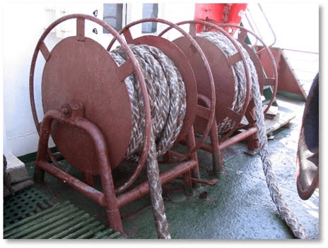 Rice. 14 Storing the cable on the views
  Rice. 15 Cable storage on banquets
 Throwing ends (throwouts) and fenders. Parts of the mooring device also include throwing ends and fenders. The throwing end is made from a line about 25 m long. At one end there is a piebald - a canvas bag filled with sand (Fig. 16).
 Rice. 16 Prepared for mooring workplace: 1 - cable; 2 - ejection; 3 - portable chain stopper
 Fenders are used to protect the ship's hull from damage during mooring. Soft fenders are most often made from braided old plant rope. Cork fenders are also used, which are a small spherical bag filled with small cork. Recently, pneumatic fenders have been increasingly used.
Mooring mechanisms. Spikes, mooring simple and automatic winches, and windlasses (for working with bow mooring lines) are used as mooring mechanisms for selecting and tightening mooring lines. Mooring capstans are installed to work with stern mooring lines. They take up little space on the deck; the capstan drive is located below the deck (Fig. 17).
 Rice. 17 Mooring capstan
 On the forecastle, windlass mooring turrets are used to remove mooring ropes (Fig. 18). Automatic mooring winches can be installed to work with stern and bow moorings (Fig. 19). The mooring line is permanently located on the winch drum; it is not required preliminary preparation before feeding and transferring to bollards after tightening. An automatic winch independently unwinds the moorings when it is over-tensioned or picks it up if the moorings have become slack.
 Rice. 18 Using the windlass head
  Rice. 19 Automatic winches
 The mooring cable selected using the mechanism is transferred to the bollards and secured. To prevent it from being etched when moving the cable, a stopper is first placed on it (Fig. 20).
 Rice. 20 Portable stoppers: a) - chain; b) - vegetable; c) - synthetic
 The stopper is attached to the eye at the base of the bollard or to the butt on the deck of the ship (Fig. 21). When working with steel mooring lines, you should use chain stoppers with a chain length of at least 2 m, a caliber of 10 mm and a plant cable at least 1.5 m long at the running end (Fig. 22). The use of chain stoppers for vegetable and synthetic cables is unacceptable.
 Rice. 21. Attaching the portable stopper to the bollard
  Rice. 22 Holding the mooring rope with a stopper
 The stopper is pulled along the mooring line in the direction of tension. When the mooring line is secured to the stopper, you should not abruptly release the cable from the capstan or capstan, so as not to jerk the stopper off. The mooring lines should first be carefully set by moving the capstan or windlass in reverse, without removing the hoses from the drum, and only after making sure that the stopper securely holds the mooring lines, quickly transfer the latter to the bollard.
On larger vessels, stationary stops can be used, which are installed on the deck between the hawse or bale strip and the bollard. Selecting and securing mooring ropes is greatly simplified when using bollards with rotating bollards. The mooring lines are placed in figure eights on the bollard bollard and fed to the windlass head. When the cable is pulled out, the bollard bollards rotate, allowing the cable to pass freely. After removing the cable from the windlass head, it will not be pulled out, since the bollards have a stopper that prevents them from turning in the opposite direction.
Suggested reading:
All components and parts of the mooring device (bollards, bitings, cleats, etc.) must be securely fastened to the hull set. Weakness of fastening (swinging) is not allowed.
In the bulwarks, near the bollards, holes are made - mooring fairleads.
If there is no bulwark, then instead of fairleads, bale strips, less often staples or cleats, are installed. Fairleads, bale strips, and shackles are used to guide mooring lines in the required directions.
All bollards, cleats, bale strips, etc. must correspond to the diameters of the cables.
Mooring ropes can be vegetable, synthetic and steel. On small vessels it is better to use vegetable and synthetic mooring ropes. Work with mooring ropes should be done without unnecessary fuss, quickly and correctly. Care must be taken to ensure that hands or feet do not get caught in the loops (pegs) of the cable.
You should know the meaning of the terms “poison” and “choose”. Loosening the mooring cable is called pickling it, and tightening the cable or stuffing it is called hauling it out. When mooring, the cable must be laid on the bollards, ducks
In this case, the person working with the cable must have enough strength to hold or move the cable with his hands. Whether the cable is being pickled or pulled out or it is already secured at the end of mooring, you must always be ready to instantly release or release the mooring cable, remove the last of the applied hoses or, conversely, throw on the hose to prevent the rope from being released. All this is achieved with practice.
When mooring the boat, its sides must be protected from impacts against the pier or the hull of another vessel, for which fenders are thrown from the sides of the boat.
Fenders can be soft or wooden. Soft ones are woven from cables or made from scraps of tires. A wooden fender is made from a short round log and suspended vertically on a cable to the side or superstructure of the vessel.
Wooden fenders should not be used on small vessels. If there is no fender along the side, wooden fenders cannot be used, as the side may be pressed in or the collar on the boats may be damaged.
During movement, fenders must be retracted inside the vessel: in no case should they hang over the sides. Fenders or ends hanging unnecessarily overboard are a sign of low maritime culture of the navigator.
Softening the blows and protecting the hull from damage can be achieved by tightening the side - from the stem to the stern - with a thick plant cable.
A sufficient number of mooring lines must be provided to the shore or to another vessel to ensure safe anchorage. It depends on the size of the vessel, mooring location, hydrometeorological conditions, etc.
Mooring ropes can fray and break due to the rocking of the vessel during waves, the rise and fall of water, ebb and flow of tides, and wave formation from passing ships.
An unreleased cable during a decrease in water can cause the vessel to hang or roll strongly, and when lowering due to a large decrease in water (in the locks), the vessel can capsize. A cable that is not released in a timely manner during the arrival of water causes the boat to touch the protrusions of the pier and damage to the hull from the list and trim.
Immediately after making a decision about mooring, you need to outline where to moor the boat, where to moor it (are there bollards, mooring devices, poles, eyelets, etc. on the shore). If there are other vessels near the proposed mooring site, you need to make sure that they do not intend to resume movement. Before mooring, you need to check the mooring lines and remove all foreign objects that interfere with mooring.
If the mooring place is unknown and not equipped, then mooring must be done carefully, slow down the boat when approaching the shore, and measure the depths.
It is advisable when approaching an unknown mooring place with the bow to make a slight trim on the bow (for example, moving people to the spit). You should avoid mooring and parking near steep, steep banks, especially clayey, sandy and devoid of vegetation, as they are easily deformed and can suddenly collapse into the water.
Particularly dangerous are landslide areas of the banks, which can be recognized by cracks along the river edge and small, often located terraces or steps descending to the water.
When approaching the mooring, the moment of stopping the propeller operation must be selected depending on the inertia of the vessel so that the vessel approaches the mooring place by inertia.
When approaching the pier on the starboard side with a conventional starboard propeller, you need to wait until you arrive at the place, and then reverse to pull the stern to the pier due to suction.
In this case, the bow will move somewhat away from the pier (Fig. 118).
The reverse gear dampens the forward movement, the rudder is set straight, the ends are brought in, and the mooring is completed.
This maneuver allows you to approach the pier broadside at an angle of up to 25° (the left pitch propeller produces the opposite effect).
When approaching the pier on the starboard side with a right-hand rotating propeller, it is necessary to go to the mooring place at low speed parallel to the pier and, not reaching the place by at least one or two lengths of the ship's hull, stop the car.
If the ship stops moving forward by inertia and stops obeying the rudder, it is necessary to resume forward engine operation for a while. If the vessel begins to pass the mooring site or level with it, you need to back up and put the rudder on the starboard side.
If it is too late to do this or it is clear that this action will not bring positive results, then you need to move forward, turn around and approach the mooring site again.
For example, moving downstream of a river, the boat must land on a concave bank (ditch) in a strong current. The boat must pass by the mooring site, turn back and land, going against the current. Turning back, as a rule, needs to be done from the concave to the convex bank.

Rice. 120 Approach of a motor boat with its bow to the shore
If there is a headwind, you need to approach at an angle of 10-20° to the pier.
Particular care must be taken to maneuver the boat and correctly calculate its inertia during dump and pressure winds (Fig. 119).
If the boat maintains forward motion, then, as a rule, even in a very strong wind, it has the full opportunity to immediately approach the pier and moor. To do this, you need to approach the pier at an acute angle until the ship touches it with the bow. You just need to ensure quick supply and fastening of the moorings. In case of strong wind, premature termination of the propeller operation will cause the wind to blow the vessel away from the mooring site.
In a downwind, it is much more difficult for a slow-moving boat with a shallow draft and high freeboard to dock, especially in rough seas, than in a bad wind. Mooring on such a boat in significant waves and downwind is carried out using an anchor released from the bow or stern of the boat, previously deployed against the wind and waves (see § 56).
The place where the anchor is released must correspond to the place where the vessel is moored, and the length of the main rope being released must allow it to be approached to the pier. After approaching the pier, the boat unmoors if it is not hit by a wave against the wall. Mooring a boat with a superstructure that has a large windage area is especially difficult.
If there is one person on board such a boat, combining work at the helm and the engine, then it is difficult, and sometimes impossible, for him to simultaneously perform mooring and steering the boat. Even a short-term leaving of the steering position by the helmsman in order to apply mooring lines in a strong off-wind wind ends in failure, because the boat is thrown away from the pier by the wind.
It is better to approach ships at anchor from the leeward side, having previously specified the location of the anchor and anchor rope. Motor boats and boats approach the shore with their bows, or, as they say, with their bows to the shore (Fig. 120). With this approach, you should turn off the engine in advance, taking into account the inertia of the vessel, so that the vessel easily crashes into shores. If the boat approaches the shore in a certain place, then you can create a trim to the stern, then the bow of the vessel will come out of the water onto the shore more.
When approaching an unknown section of the coast, it is necessary to check the depth with a meter rod, which makes it possible to know both the depth and the nature of the soil. It is difficult to do this from a small boat, but when a boat approaches, it is necessary to do this.
The person measuring the depth must be aware that if the vessel suddenly stops from contact with an underwater obstacle, it may fall.
When approaching an unknown place, it is necessary to trim the bow.
After approaching the shore, you need to secure the mooring line on the shore, and if this is impossible due to the lack of mooring devices - bollards, eyelets or other suitable objects, then you need to take the anchor ashore. Rice. 121.

Vessel mooring
Approaching with the bow to the shore can be practiced in a weak current; in a strong current, the ship will turn parallel to the shore so that the stern is downstream. Approaching the shore during waves is carried out in compliance with special rules (see § 56).
Mooring operations can be very varied and depend on many factors. The ability to moor correctly and quickly depends on the experience of the amateur and characterizes his navigational skills.
However, when mooring, you should not approach the pier at high speed in order to avoid damage to the vessel (in case of engine failure or unexpected delays in changing the operating mode necessary to perform the maneuver). Unnecessary recklessness often leads not only to damage to one's own vessel, but also to damage to the pier, other vessels, injuries and loss of life. When mooring, the boatmaster is required to: great attention
, ingenuity and experience. Mooring using a template is unacceptable, especially for a boat with great maneuverability. The external conditions in which a ship must be moored are very diverse and it is impossible to foresee all of them in advance.
Mooring should be considered completed when the navigator checks the fastening of the moorings on the ship and on the shore, the depth under the bottom, makes sure that the mooring corresponds to changes in the water horizon and that passing and mooring ships will not damage the boat. The best position for a vessel when moored for a long time is a generally accepted mooring. small vessels
When moored in this way, the deep-draft parts of the vessel and the propeller are farthest from the shore and the movement of the boat by wind and current is excluded. Vessel the best way plays out on the wave.
Rice. 122. Mooring of ships at anchor near the shore

For parking near a deep shore or near a pier, the vessel can be positioned with its stern towards the shore. Then permanent parking can be organized as shown in the figure (Fig. 120, b).
At a distance greater than the length of the ship's hull from the pier or a suitable shore, a pile is driven in, to which an eye, a block is attached, or a groove is made on the pile. The cable from the bow of the vessel is fed to the shore, first passed through an eye or through a groove on a pile.
The vessel must be moved away from the shore by this forward moving cable to a sufficiently large distance so that its hull or any part does not rub against the pier.
The depth must also be sufficient to guarantee safety when the water horizon fluctuates from drying out and impacts on the ground by the underwater part and, in particular, by the rudder. From the stern of the vessel, mooring lines must be supplied to the pier and secured after securing the bow mooring line, which also goes through the pile to the pier.
For long-term mooring, the boat can be placed in the corner of the pier behind the bow and stern moorings, supplied to the pier (Fig. 121, d).
Lagoon parking of small vessels is used as a temporary or even short-term berth for boarding or disembarking people at the pier or on another vessel.
If it is necessary to become a log to the pier, the bow and stern mooring lines are strengthened respectively on the pier at an angle forward and backward.
In case of strong wind or waves, one or two additional cables are supplied from the sides of motor yachts. Methods of fastening the cable on the pier (pier) when setting a log are shown in Fig. 121, a. Parking side by side, especially during rough weather, should be avoided.
When moored at the pier, you must constantly monitor the boat, changes in its draft, fluctuations in water horizons, and accordingly adjust or select mooring lines. Parking can also be organized in cases where there is no specially equipped berth or a larger number of vessels need to be accommodated in the berth water area. Schemes of such a vessel arrangement are shown in Fig. 122. Position A
ensures that the vessel moves on the wave and prevents it from hitting the shore. Metal ballast on the anchor rope (position b) acts as a shock absorber for the vessel to bounce back on the wave and, in addition, brings the rope into a vertical position, which is necessary in places of large traffic and congestion of ships. To position the vessel is driven in a manner similar to that shown in Fig. 122,6, those. a moving cable attached not to the pile, but to the anchor.
In Fig. 123 shows methods for supplying and securing mooring lines from the ship to the bollard and eyes. In all cases of securing mooring lines to shore bollards and eyelets, it is imperative to provide for their quick release when necessary.
Small wooden, metal and plastic boats for long-term and sometimes temporary parking should be taken far enough to the shore so that the surf cannot turn them over and break them. It is recommended to cover boats and motorboats with a tarpaulin so that water from the tarpaulin flows overboard and not into the vessel.
Rice. 123. Fastening mooring ropes on shore

Departure of a boat from the pier, as a rule, does not present any particular difficulty. In any case, leaving the pier is easier than approaching it. When leaving the pier, when ready or when the engine is turned on, the mooring lines are released and the boat moves forward.


